Interfacing Arduino with 13.56MHz ISO15693 RFID tags using NXP PN5180 modules
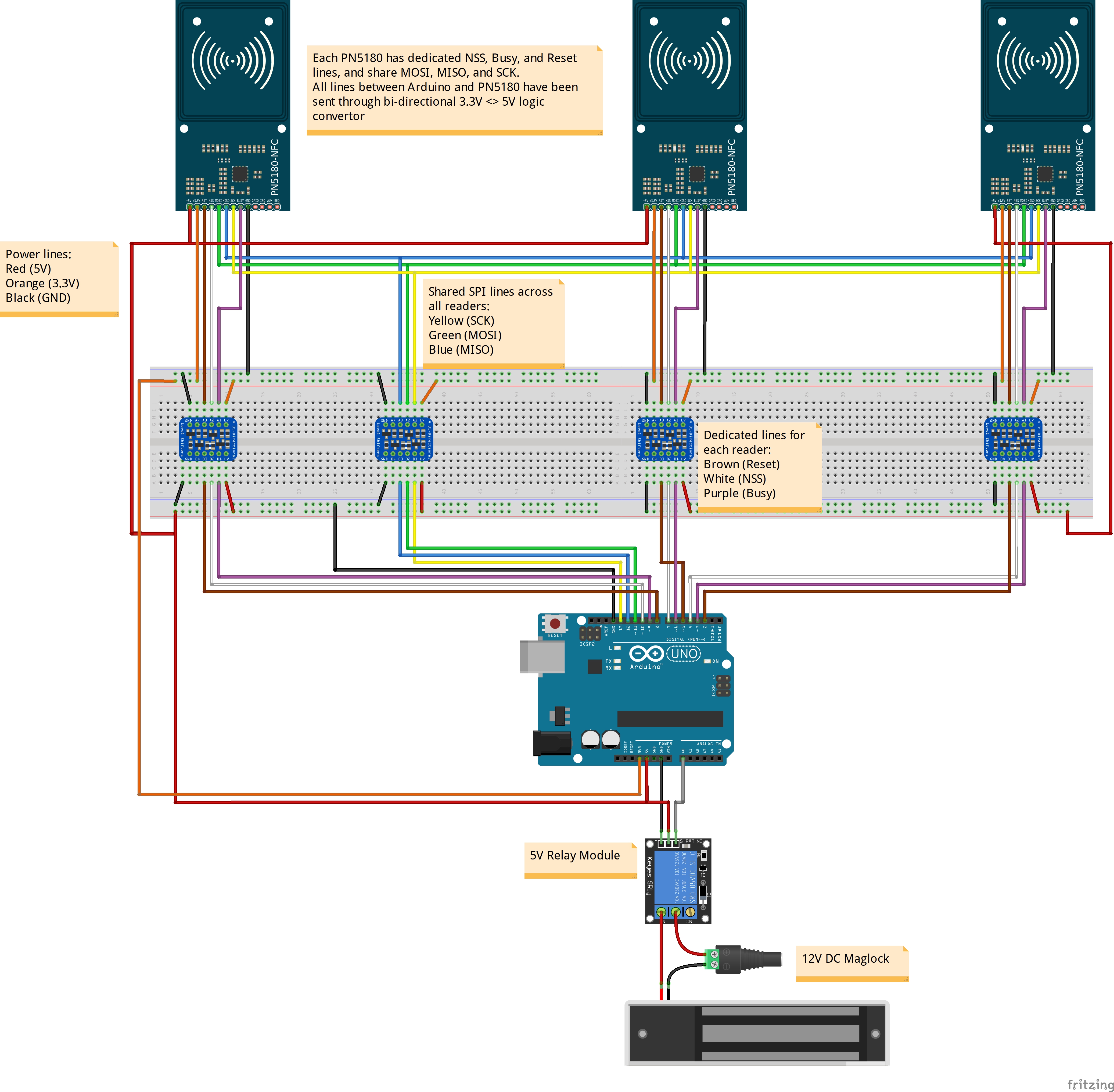
The PN5180 reader uses the ISO15693 "vicinity card" protocol, which offers a significantly longer read range than the ISO14443 "proximity card" protocol seen in other common RFID readers such as MFRC522 or PN532. It uses SPI interface, which can be shared between a number of readers. Each reader also requires their own slave select, reset, and busy lines. For a comparison of alternative readers, see https://www.patreon.com/posts/rfid-roundup-23115452
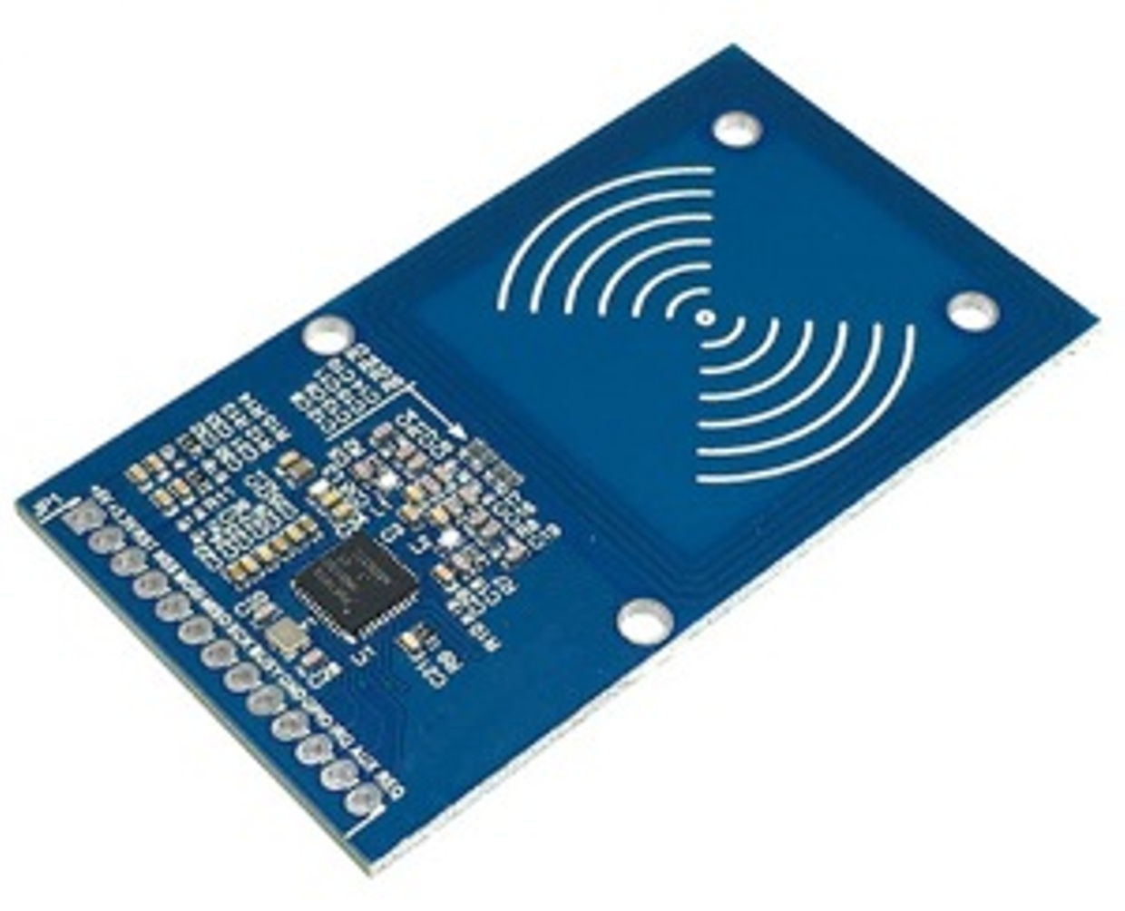
- PN5180 Module ~£8
- Arduino ~£3
There are 13 pins on the 5180 board, as follows:
- +5V : +5V DC supply
- +3.3V : +3.3V DC supply
- RST : Reset line from Arduino *
- NSS : (Not) Slave Select is pulled LOW when communicating with Arduino *
- MOSI : Master-Out, Slave-In used for transmitting data from Arduino to the reader *
- MISO : Master-In, Slave-Out used for transmitting data from the reader to the Arduino
- SCK : System Clock signal sent from Arduino *
- BUSY : Used by reader to report busy state
- GND : Ground
- GPIO : Can be used as general-purpose output pin from the reader (e.g. to power an LED)
- IRQ : Not required
- AUX : Not required
- REQ : Not required
Arduino UNO/Nano/Mega operates at 5V logic. However, the PN5180 works at 3.3V logic level, and is not 5V tolerant. If using one of these microprocessors:
-
You must use a 5V <-> 3.3V level shifter on any lines that send HIGH output from the Arduino to the PN5180. These are RST, NSS, MOSI, and SCK marked with an asterisk in the list above.
-
You may use a 3.3V <-> 5V level shifter on those lines that send HIGH output from the PN5180 to the Arduino (MISO, BUSY) though this is not generally necessary - a HIGH 3.3V signal will normally be recognised as a HIGH signal on a 5V system too.
-
MOSI, MISO, and SCK lines are shared between all readers, and use Arduino SPI pins 11(MOSI), 12(MISO), and 13(SCK).
-
NSS, BUSY, and RESET lines must be assigned to unique GPIO pins for each reader.