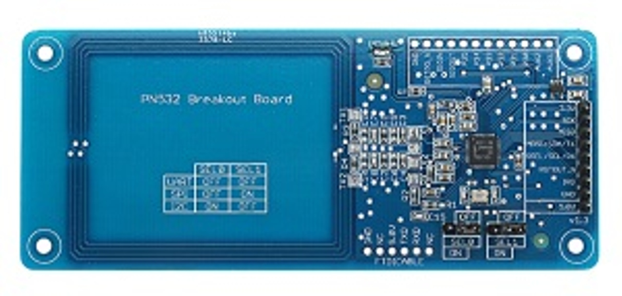
Connecting from an Arduino (UNO/Nano etc.) to a PN532 Breakout Board, which can read ISO14443 RFID tags @13.56MHz, via a SPI, I2C, or UART interface. For a comparison of alternative readers, see https://www.patreon.com/posts/rfid-roundup-23115452
- PN532 Module ~£9
- Arduino ~£3
- Bi-directional 3.3V <> 5V TTL convertor ~£0.50
If using the SPI interface, the module should be wired as follows:
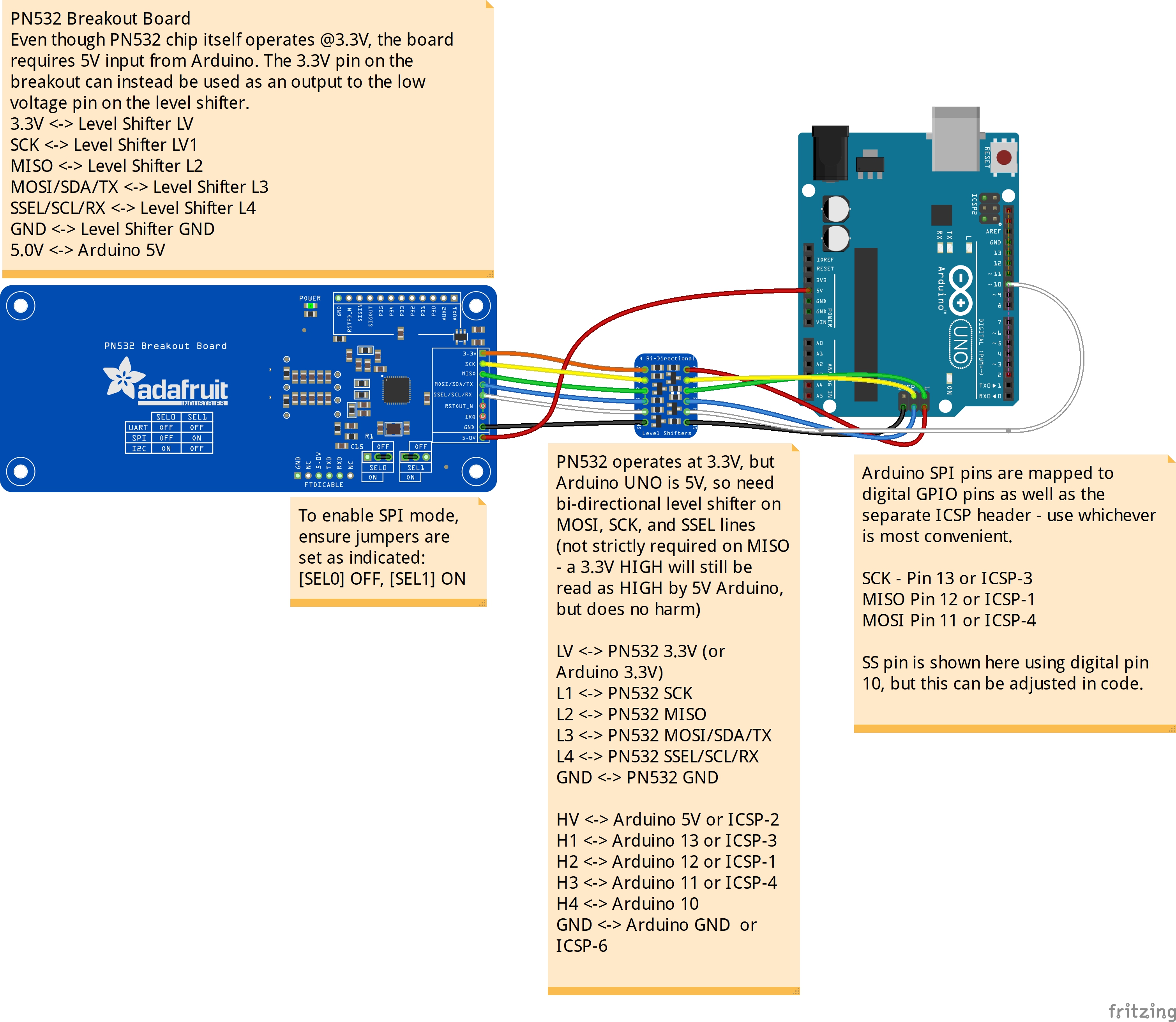 SPI is faster than I2C (typically 20MHz-vs-400kHz), though it requires slightly more complicated wiring. Each SPI slave device requires dedicated lines for data in (MOSI), data out (MISO), and clock signal from the master. They also have a unique slave select line, which is pulled LOW for the device that the master is currently communicating with. So, to connect n readers to the Arduino requires (3 + n) available pins on the Arduino - in the absence of any other devices, an Arduino UNO/Nano can therefore control around 15 SPI devices (although this can be extended through the use of a multiplexer).
Since the logic level of the PN532 is 3.3V, any output lines from a 5V Arduino (UNO, Nano, etc.), i.e. the MOSI, clock, and SS lines should all be converted down to 3.3V. The input into the Arduino does not strictly require stepping up - a HIGH logic signal on a 3.3V device will typically still be registered as a HIGH logic signal on a 5V device, though it does no hamr to do so.
SPI is faster than I2C (typically 20MHz-vs-400kHz), though it requires slightly more complicated wiring. Each SPI slave device requires dedicated lines for data in (MOSI), data out (MISO), and clock signal from the master. They also have a unique slave select line, which is pulled LOW for the device that the master is currently communicating with. So, to connect n readers to the Arduino requires (3 + n) available pins on the Arduino - in the absence of any other devices, an Arduino UNO/Nano can therefore control around 15 SPI devices (although this can be extended through the use of a multiplexer).
Since the logic level of the PN532 is 3.3V, any output lines from a 5V Arduino (UNO, Nano, etc.), i.e. the MOSI, clock, and SS lines should all be converted down to 3.3V. The input into the Arduino does not strictly require stepping up - a HIGH logic signal on a 3.3V device will typically still be registered as a HIGH logic signal on a 5V device, though it does no hamr to do so.
If using the I2C interface, the module should be wired as follows:
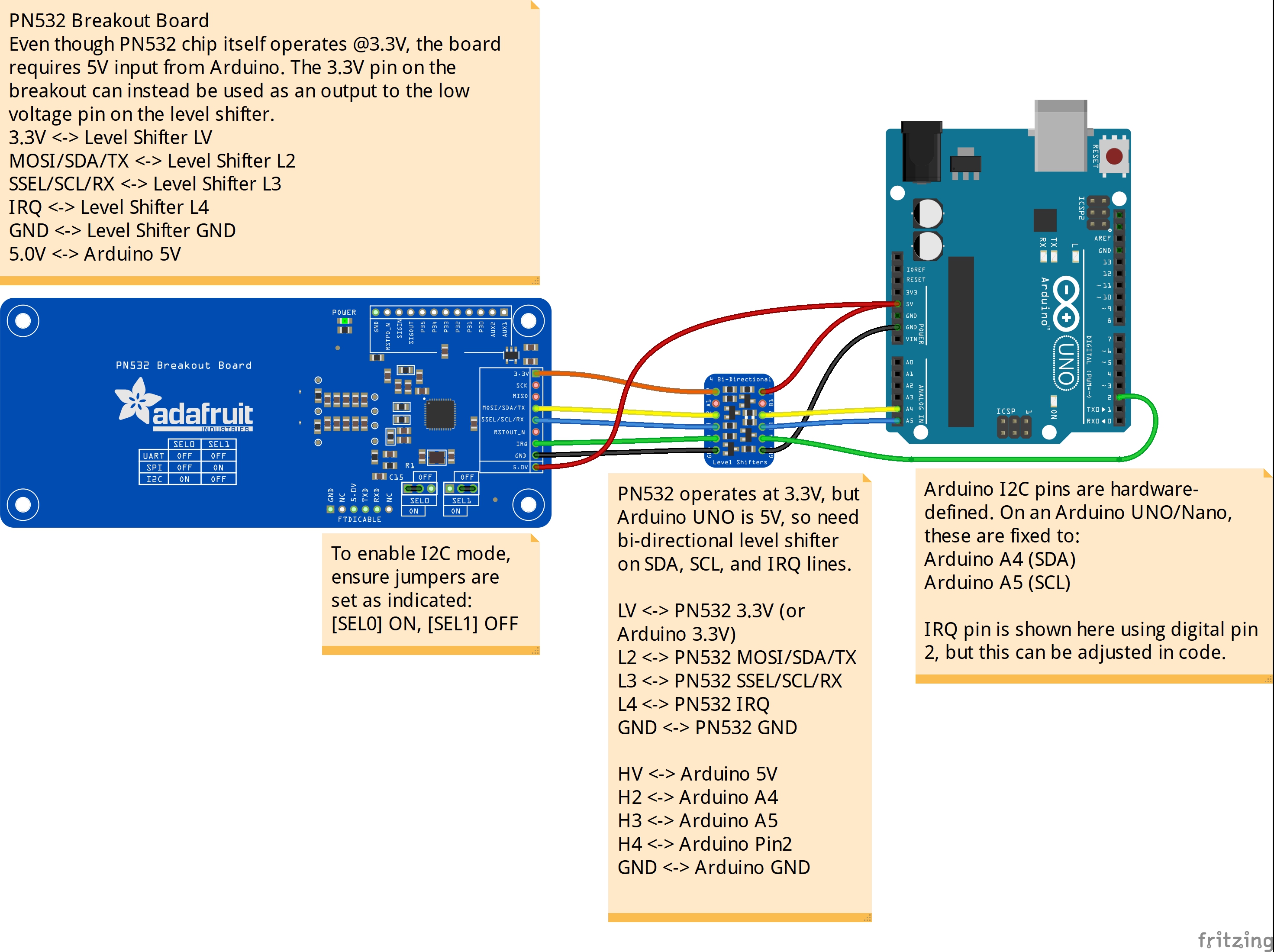 In theory, I2C should be a more convenient interface to use if you wanted to wire multiple readers to your Arduino - it requires only a pair of wires (clock (SCL) and data (SDL), both bi-directional) to be connected to each device, and communication is routed to the correct reader using a unique device address. Up to 127 slave devices can be connected BUT it turns out that, on this particular board, the I2C address is fixed at 0x48 - so there is no way to have more than one reader attached via I2C as there would be no way to uniquely identify them.