Driver electronics for the Octopi and Squid microscope families.

This repository contains the design files for printed circuit boards (PCBs) for driving the sensors and actuators of the Octopi and Squid families of microscopes.
Octopi, short for Open configurable high-throughput imaging platform for infectious disease diagnosis, is a low-cost and reconfigurable autonomous microscopy platform capable of automated slide scanning and correlated bright-field and fluorescence imaging. It has been developed for malaria microscopy, and its modular design also provides a framework for new disease-specific modules to be developed.
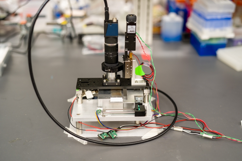
Squid, short for Simplifying quantitative imaging platform development and deployment, is a toolkit for implementing research microscopes with advanced imaging capabilities comparable to what's available in commercial solutions, but at a fraction of the cost and with much higher portability. Squid provides a full suite of hardware and software components for rapidly configuring high-performance microscopes tailored to users' applications with reduced cost, effort, and turnaround time. Besides increasing accessibility of research microscopes and available microscope hours to labs, it is also designed to simplify development and dissemination of new or otherwise advanced microscopy techniques.
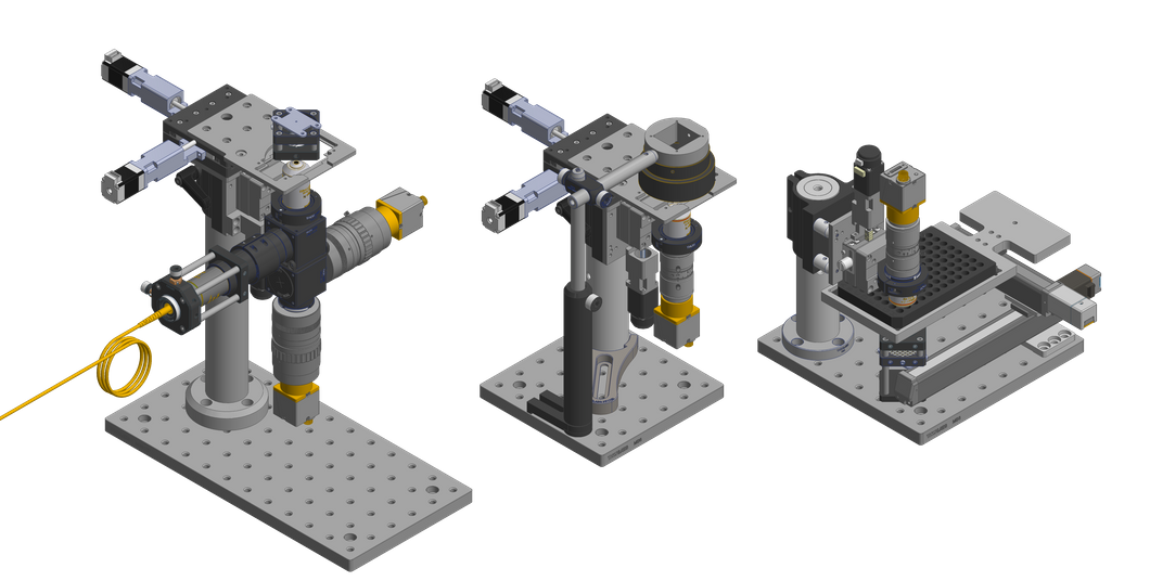
Because the modules of the Octopi and Squid microscopes contain various sensors and actuators which need to be electronically driven and integrated into a complete system, the Squid project also provides printed circuit boards for interfacing and controlling these modules. This repository contains the designs for printed circuit boards needed to drive these microscopes.
Subsystems of the driver electronics are organized as discrete modules which are integrated into the overall system by being stacked. These modules are PCBs which are electrically connected through board-to-board connectors and mechanically connected through standoffs at their corners, reminiscent of the PC/104 family of standards for embedded computer form factors and communication buses. The stacking system is called the Octopi Driver Stack (ODS), while the boards which are stacked are called planes. There are also boards which are not part of the stack but rather connect to planes; because these are peripheral to the system, they are called peripheral boards. Planes and peripheral boards may also have smaller circuit boards mounted onto them, which are called daughter boards.
Each board is given a two-part name code, consisting of a name code for the type of board followed by a name code for the specific design of the board. Each board is associated with a version of the Octopi Driver Stack (which provides information about compatibility between planes) and an independent version of the board itself (which provides information about functionality within planes and connector interfaces between the plane and daughter boards or peripheral boards). Version numbers follow the Sematic Versioning 2.0.0 specification.
ODSv1.0.0 consists of planes measuring 150 mm x 150 mm which are all connected to each other by shared data and power bus lines for all GPIO provided by a microcontroller. Each corner of a plane has a mounting hole sized for an M3 standoff; these mounting holes are spaced 140 mm apart, with 5 mm between the center of each hole and its two nearest edges. Each corner of the plane is a rounded corner of radius 5 mm. The four edges of each plane are allocated to different functionalities:
- The front edge contains indicator LEDs, as well as connectors and circuity for the shared data and power bus lines which connect all planes together in a stack. In this project, these connectors and circuitry are collectively called the backbone of ODSv1.0.0; at the level of hardware these elements are just a bus like in the PC/104 architecture, but our project uses the term "backbone" so that we can use the word "bus" only to describe standard buses (e.g. SPI, I2C) which the "backbone" is organized around. Each plane has two connectors for the backbone system, and they are at the same position but on opposite faces of the PCB. On the bottom face, a Hirose FunctionMAX FX20-120S-0.5SV receptacle is used. On the top face, a Hirose FunctionMax FX20-120P-0.5SV15 header or FX20-120P-0.5SV20 header is used, depending on the height of components on the top face of the board. These connectors are positioned so that their centers are 55 mm from the left edge of the plane and 35 mm from the front edge of the plane. The connectors are oriented so that their long edges are parallel with the front and rear edges of the plane, and so that pin 1 is farthest from the left-front corner of the plane.
- The left edge contains input and output power connectors.
- The right edge contains analog and digital signal connectors.
- The rear edge contains rarely-used or rarely-accessed connectors.
ODSv1.0.0 consists of a single central processing plane (board type name code PP, short for Processing Plane), which is stacked together with other planes consisting mainly of SPI devices, such as for:
- Motion control (board type name code
MP, short for Motion Plane) - Camera synchronization (board type name code
CP, short for Camera Plane) - Illumination control (board type name code
IP, short for Illumination Plane) - Thermal control (board type name code
TP, short for Thermal Plane) - Sensing (board type name code
SP, short for Sensing Plane) - Fluids control (board type name code
FP, short for Fluids Plane) - I/O prototyping breakout (board type name code
BP, short for Breakout Plane)
The SPI devices on these planes are addressed through a hierarchical chip-select multiplexing scheme to enable composition of planes for customization, reconfiguration, and expansion of capabilities.
Every plane is separated by a distance of either 15 mm or 20 mm from the plane above it, depending on the height of components on the top face of the plane. All tall components should only be on the top face of the plane.
To set up your computer for using this repository, you will need to install KiCad version 5.1.9; note that this repository relies on KiCad footprints which exist in 5.1.9 and not in earlier versions. You should have the default symbol, footprint, and 3-D model libraries provided by KiCad. References to custom symbols, footprints, and 3-D models will work out-of-the-box, as they are all provided in this repository and referenced in KiCad relative to the ${KIPRJMOD} environment variable.
To prepare 3D models for components, you will need to download FreeCAD 0.19 and install the KiCad StepUp workbench.
This repository is structured so that every board has its own top-level directory with the following naming scheme:
- Templates:
ODSv<Octopi Driver Stack version>-<template type name code>-<specific design name code, if any> - Planes:
ODSv<Octopi Driver Stack version>-<board type name code>-<specific design name code> - Peripheral boards and daughter boards:
<board type name code>-<specific design name code>
Each directory has a short README describing the contents of the directory. All boards are designed in KiCad. Only the most recent version of each board is included at the HEAD of the repository; older versions of boards are tagged on Git and archived in this repository's Github Releases. You can review the design files without KiCad, by viewing this project on CADLab.io.
Templates are provided as starters to copy for creating new boards. For more information, refer to ODSv1.0.0-BT/README.md.
All footprints, documentation, CAD models, and KiCad libraries for components and daughter boards used with the ODSv1.0.0 boards are available in the Parts directory.
Unit tests for the ODSv1.0.0 boards are available in the Tests directory. These are Arduino sketches intended to be uploaded to the Teensy for basic verification of board functionality.
A KiCad project which mechanically integrates all planes in the ODSv1.0.0 stack for 3D rendering is in the ODSv1.0.0 directory.
This repository will provide planes and boards which implement a core set of functionalities. When you need to prototype new functionalities integrated into the driver stack, you should the ODSv1.0.0-BP-Jmp breakout plane, which is designed to enable prototyping. To start out, just connect the components you need with jumper wires to the various header pins on that plane; whenever possible, you should prefer using the SPI bus and the pins in the GPIO section. If you run out of available GPIO pins, if you need to assemble many copies of your prototype, or if you need more breakouts, then you should integrate your components as a new plane and, ideally, submit your plane to this repository. To do so:
- Wherever possible, shift your use of GPIO pins on BP-Jmp to the plane's SPI I/O expanders for digital I/O, ADC, and DAC. The headers for those components are in the middle of the plane.
- Create a new plane as a copy of the ODSv1.0.0-BT starter template. For more information, refer to ODSv1.0.0-BT/README.md.
- Add the standardized SPI I/O expanders, which are used in the BP-Jmp plane, to meet your GPIO needs; and add other SPI devices as needed. You will need to add the standardized pull-up resistor on the CS pin of each SPI device. For devices whose DOUT/DO/MISO/CIPO pins are not tri-state, you will need to add the standardized tri-state buffer between the pin and the CIPO line, which should be controlled by the same demultiplexed DCS line as the SPI device's CS pin; this tri-state buffer also needs a standardized bypass capacitor.
- Add I2C devices if no alternative with an SPI interface is available. You will need to add the standardized bus switch between the SDA/SCL pins of each device and the SDA/SCL bus, and you should control the bus switch using one of the demultiplexed DCS lines; you will need to add the standardized pull-up resistor onto this line. This bus switch also needs a standardized bypass capacitor.
Where appropriate, you should delegate functions in your plane onto daughter boards. For example, if there is a particularly complex or expensive subsystem which you need to be able to swap out or test independently, or if you are reusing the same subsystem multiple times, you may want to make daughter board PCBs - each with one copy of the subsystem - which you can plug in to your new plane.
Snapshots of boards for fabrication/assembly are tagged and associated with releases. Each release comes with the following attachments:
- The schematic diagram (
*-schematic.pdf) - A drawing of the footprints and silkscreens on the top face of the board (
*-silk-top.pdf) - A 2-D rendering of the top face of the board, including copper and silkscreens (
*-board-*-top.png) - Gerber and drill files for fabricating the board with PCBway (
*-gerb.zip) - A complete archive of all diagrams, drawings, renderings, and fabrication and assembly files for the board (
*-docs-rev*.zip)
The assets attached with releases are automatically generated from a Github Actions workflow in this repository. This workflow is automatically run for commits in all pull requests and for any pushed commit.
The workflow can also be manually triggered from the KiCad Exports page, with the following parameters:
- Branch: Use this to specify which branch to use for the workflow.
- Git ref: Use this to specify which commit of the design files to export. If you leave it blank, it will do an export from the most recent commit on the selected branch. If you give it a tag name or commit SHA hash, the workflow will export files from the corresponding commit.
- Boards: Use this to specify which boards to export. If you leave it blank, it will export all boards. If you want to export multiple boards, separate their names with spaces (e.g.
ODSv1.0.0-PP-T41 ODSv1.0.0-CP-5x). - Variants: Use this to specify which variants of each board to export. If you leave it blank, it will export only the default variant of all specified boards. You should only use this field if you have specified exactly one board to export; otherwise, leave it blank. If you want to export multiple variants, separate them with spaces (e.g.
Default Pufferfish).
Currently the maintainer of this repository is Ethan Li.
The ODSv1.0.0 system is still at an early stage, and we do not have capacity to provide extensive support to people interested in contributing to the project. We have not yet set up public infrastructure for users to ask questions. We will look at pull requests but we do not yet have a process for accepting them. However, we are excited to build a community of contributors, so as this repository matures we will work to set up these processes and systems.
All contributions should be made through pull-requests. Before a pull request is merged, every author or co-author of the pull request must add a comment answering the following questions:
- This project is licensed under Apache License v2.0 for any software, and Solderpad Hardware License v2.1 for any hardware - do you agree that your contributions to this project will be under these licenses, too? Indicate response here (the contributions will only be accepted if all co-authors agree)
- Were any of these contributions also part of work you did for an employer or a client? If so, do you have their permission to release it? Indicate responses to both questions here (the contributions will only be accepted if the answer to the first question is "no", or when the answer to the second question is "yes").
- Does this work include, or is it based on, any third-party work which you did not create? If so, what is it licensed under, and what modifications, if any, did you make to it? Indicate response here (before the contributions are accepted, use of those third-party works will need to be recorded, license compatibility will need to be checked, and license notices will need to be retained within the repository; we are happy to support you in getting these things in order)
Copyright Prakash Lab and the Octopi project contributors.
SPDX-License-Identifier: Apache-2.0 WITH SHL-2.1
Except where otherwise indicated, all work in this repository is licensed under the Solderpad Hardware License v2.1 (the “License”); you may not use files except in compliance with the License, or, at your option, the Apache License version 2.0. You may obtain a copy of the License at https://solderpad.org/licenses/SHL-2.1/
Unless required by applicable law or agreed to in writing, any work distributed under the License is distributed on an “AS IS” BASIS, WITHOUT WARRANTIES OR CONDITIONS OF ANY KIND, either express or implied. See the License for the specific language governing permissions and limitations under the License.