System Identification of the Robot
- Open the WPILIB VS Code
- Click on the 3 dots in the upper right hand corner of the window
- Select Start Tool
- Select SysId
- Configure your settings
- PLEASE MAKE SURE THAT YOU ARE CONNECTED TO THE ROBOT
- Go to the Generator Tab
- For Team IP type in your team number
- For Analysis Type, select Drivetrain
- For Motor Controller Pair 0 select your type of motor
- Select the CAN ID for the front motors on each side, and choose which ones are inverted
- Click on the plus side by the Motor heading to create settings for the back motors
- Do the same thing in the next 5 options, these will be for the back motors
- For the Encoder Selection Choose how the Encoder is sending data to the robot
- For the Gyro Subheading Select what type of Gyro the team is using and from that what SPI Port
- For the Encoder Parameters Counts Per Revolution Should be left as is the Gearing should be changed to the correct gearing for the robot(PLEASE NOTE: if the gearing is for instance 10.71 then 10.71 will go in the left box and 1 will go in the right box) *** After the previous step please click the deploy button in the generator tab, this should be at the top of the tab. Another tab should pop up that shows the process of the configuration being deployed***
- Go to the Logger Tab
- For the mode select Client
- Make sure the team number is the same in the team/IP box and that the Get Address from DS box is selected
- Click Apply
- For the project parameters leave everything as is. The mechanism should be drivetrain, the unit type should be meters, and the units per rotation should be 1.0000
- For Voltage Parameters leave quasistatic Ramp Rate at 0.25
- The Dynamic voltage could be left also as is, but if the Robot motors start stalling when you run this test switch the Dynamic Voltage to some lower value. In this case we found that 3.88 Volts worked for us if this happened.
- Now that all the Configurations are created the next step is to run the tests(These will be found under the logger tab under the subheading tests)
- In order to run the tests you must have the FRC Drivestation open(MAKE SURE YOU ARE CONNECTED TO THE ROBOT)
- For each test you first tab over to the autonomous window. Then select a test that has a "Not Run" Descriptor(Preferably do them in order from top to bottom)
- Click on the test name, a tab will popup inside the window that will prompt you to start the test.
- Go to the autonomous window and click enable. This should allow for the program to start working and the robot should move.
- When the Robot is getting close into an obstruction of some sort, disable the program then toggle back to the System Identification window and hit the end test button.
- Repeat Steps 7-11 for the reamining tests.
- When all of the tests are finished choose a file location to save the tests(this should be at the very bottom of the logger tab) then hit save
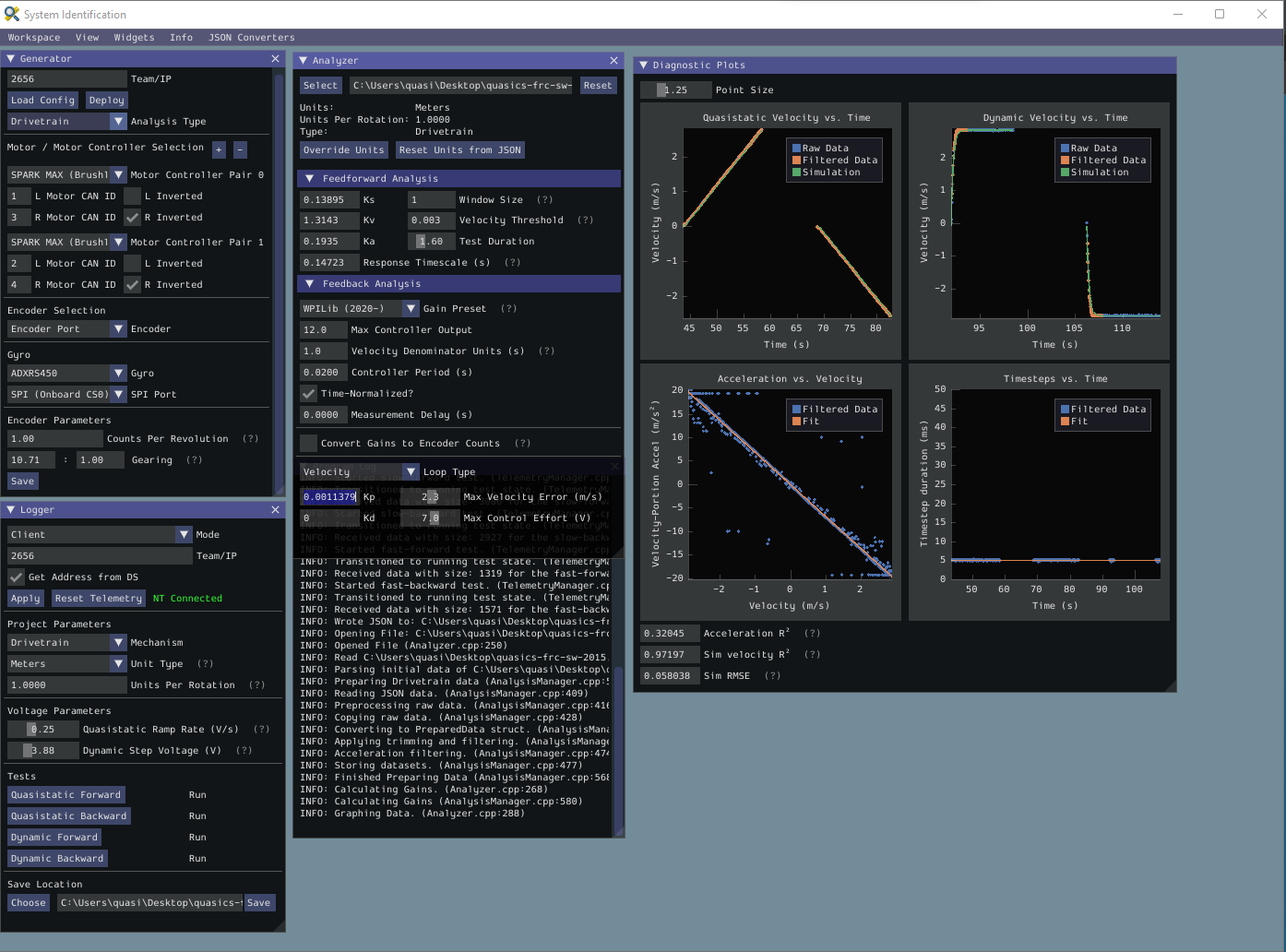
- Next go over to the Analyzer tab and click the select button at the very top of the tab
- This analysis will display to you all of the values you need for pathfinding.
- One thing that should be changed just in case is in the Analyzer tab, under the subheading Feedback Analysis, it is recommended to change the Gain Preset to the correct one.
- In the end after the identification has been done, it should look something like this.