Faster convex_hull_image polygon drawing for 2D images #2928
Conversation
Replaced `grid_points_in_poly` with calls to `skimage.draw.polygon_perimeter` and `scipy.ndimage.morphology.binary_fill_holes` in convex polygon drawing step for a 2D image.

For large 2D images (~10,000 x ~10,000 pixels), this substitution can result in a function-call-to-return speedup of more than 5x (from 23.0 sec to 4.4 sec for a particular image with about 150 convex hull edges) while producing a convex hull image that is nearly identical to the image created by the current drawing routine.  In following comments, I will compare the two results of these two routines.
|
Hello @husby036! Thanks for updating the PR. Cheers ! There are no PEP8 issues in this Pull Request. 🍻 Comment last updated on May 01, 2018 at 04:11 Hours UTC |
| @@ -2,7 +2,8 @@ | |||
| from itertools import product | |||
| import numpy as np | |||
| from scipy.spatial import ConvexHull | |||
| from ..measure.pnpoly import grid_points_in_poly | |||
There was a problem hiding this comment.
Should we make changes to grid_points_in_poly instead?
There was a problem hiding this comment.
I'm not sure which functions use that method, but if they could benefit from this speedup for drawing polygons with many edges (though I can't say at how many edges you start seeing the speedup), applying the changes there instead could work well.
|
This PR description is just perfect 🚒 . @husby036 do you see any downsides of the |
|
@soupault Thank you! It's my first PR for a public repo, so I tried to put in my best effort. I've updated the description with a test of a smaller image for comparison. The results are quite interesting -- I encourage you to take a look! In short, I found ( Without further testing, I believe the improved drawing routine should produce an image close enough to the ideal image in most cases to make the speedup benefit worth the slight chance of drawing a convex hull border that is 1-px too wide (from the ideal setting for |
|
Well, my mind is suitably boggled. I unfortunately won't have time to do a detailed review until late January (Merry Christmas, everyone! ;) but: a) the performance benefit is substantial enough that I agree with @soupault that this should definitely be included one way or another very soon, but |
|
@jni Thank you for your input, and Merry Christmas to you! I agree 100% that the deprecation path must be analyzed in a stronger fashion than simply comparing the result images pixel-by-pixel. When I have more time, I would take a look at the differences between the Pardon me for wanting to get the word out there that a speedup is possible, as it's greatly benefited me already. :) I'm actually using this faster polygon drawing routine for the processing of satellite imagery in a |
Oh we are very happy to see this!
Sounds great! |
|
Also see #931 |
|
Hi @husby036 et al! Sorry for the long delay in getting back to this. For a start, some of the tests are failing with index-out-of-bounds errors: Others are failing due to the pixel-wise difference between this PR and the expected output, as we expected. So, my suggestion:
@husby036 are you up for this? Do you know how to update a PR? Let us know if you need guidance. |
|
Hi again, @jni! No worries about the delay. I've been plowing through MATLAB code at my work since then... (has it really been 4 months? oh no) This is a good excuse for a break. ;) I am up for making the necessary changes. Thank you for providing the link to the Travis CI build log -- I didn't know I could see that! My hunch is that the current I'll do more testing soon. Still learning the whole GitHub thing, but now that I've found the nice documentation on how to run the automated testing for my modifications to skimage locally, I think I can figure it out. :) |
|
I picked up this issue on the SciPy sprint earlier in the year and figured out that the source of the mask[hull_perim_r, hull_perim_c] = True...is occurring due to the offsets = _offsets_diamond(image.ndim)
coords = (coords[:, np.newaxis, :] + offsets).reshape(-1, ndim)To explain:
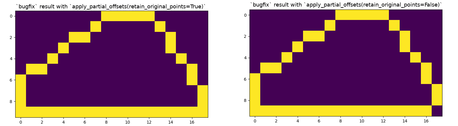
I propose that we replace line 124 with the following: coords = apply_partial_offsets(img, coords, offsets)Using the following function: def apply_partial_offsets(img, coords, offsets, retain_original_points=True):
"""
Apply the offsets only to the non-edge pixels, along with the trivial zero-offset
if `retain_original_points` is True (default: True, recommended due to corner loss).
"""
if retain_original_points:
# Insert the trivial offset of [0., 0.] into `offsets`
offsets = np.insert(offsets, 0, 0., axis=0)
row_max, col_max = np.subtract(img.shape, 1)
# bool masks for the subsets of `coords` including each edge (one edge at a time)
edge_t, edge_b = [coords[:,0] == lim for lim in (0, row_max)]
edge_l, edge_r = [coords[:,1] == lim for lim in (0, col_max)]
edge_includers = [edge_t, edge_b, edge_l, edge_r]
if retain_original_points:
dummy_edge = np.zeros_like(edge_t, dtype=bool) # False so offset always applied
edge_includers.insert(0, dummy_edge)
offset_mask = np.invert(edge_includers).T
offset_idx = np.argwhere(offset_mask.ravel()).ravel()
coords = (coords[:, np.newaxis, :] + offsets).reshape(-1, img.ndim)[offset_idx]
return coordsNotice that the penultimate line of the function essentially just repeats the original line but then filters out the indexes at which the offsets should be masked because the coordinates at that position in The
It should probably only be used in the case of the 2D convex hull, so maybe we need to add an Can anyone review these suggestions before I submit a PR? 😃 This is my first contribution to I rewrote the above function for clarity a few times, please let me know if it isn't the proper |
|
Awesome, awesome work @lmmx! Thank you for taking up the mantle on this upgrade after I let it get swept under the rug. I don't know if I can be of any assistance as I think you have a good handle on the situation now, but please let me know if I can! As I alluded to in an earlier comment, my main project of 2017 was writing an algorithm to produce a 2D concave hull image for processing of large satellite images. I might need to ask for your help to test that when the time comes to submit it to scikit-image! ;) |
Description
Replaced
grid_points_in_polywith calls toskimage.draw.polygon_perimeterandscipy.ndimage.morphology.binary_fill_holesin convex polygon drawing step for a 2D image.For large 2D images (~10,000 x ~10,000 pixels), this substitution can result in a function-call-to-return speedup of more than 5x (from 23.2 sec to 4.6 sec for the tested image that has about 150 convex hull edges) while producing a convex hull image that is nearly identical to the image created by the current drawing routine. What follows is a comparison of the
cProfileresults and convex hull images created by the two routines.Testing script
To test the differences between the two drawing routines, I ran the following script to do a cProfile on the
skimage.morphology.convex_hull_imagefunction with and without changes to the "convex_hull.py" file in myskimagepackage library. Results using the function in its current state (without my changes) are referred to as thelatestmethod, while results using the function in its faster state (with my changes) are referred to as thefastermethod. Additionally, I tested both theoffset_coordinates=Trueandoffset_coordinates=Falseoptions toconvex_hull_image.For my primary test case, I chose the following 10341 x 11441 px source image:
In this figure, yellow pixels are one/True/data pixels while purple pixels are zero/False/nodata pixels.
offset_coordinates=True
cProfile results
latest: offset_latest_cprof.txtfaster: offset_faster_cprof.txtWe see a speedup of about 5x for this large input array.
Result image comparison
Histograms show counts of pixel values with the pixel value corresponding to each histogram bar taken to be the x-axis value at the left end of the bar.
In the upper set of images, yellow pixels (value=1) are part of the convex hull while purple pixels (value=0) are not.
The lower left image titled "Difference" is an image obtained by subtracting the upper left image from the upper right image (
fasterminuslatest). Therefore, yellow pixels (value=1) are hull pixels infasterbut not hull pixels inlatest, and vice-versa for purple pixels (value=-1).The lower right image titled "Boolean Difference" is to help spot where differences in the images are located; yellow pixels (value=1) are where differences occur.
The "Difference" figure zoomed to red box:
In the "Difference" figure, yellow and purple rectangles show one-pixel differences in the border width of the drawn hull. For the
offset_coordinates=Trueoption, we assumelatestis most correct and want to minimize the total number of blue pixels. The total number of blue pixels is is approximately 10, which is good. Since there are approximately 10,000 yellow pixels in the "Difference" figure, we see thatfasteralmost always draws a thicker polygon border thanlatest.For closer inspection of the drawing routines in relation to the source image, the following "_inspection" images were created as shown in the last lines of the above testing script.
In "*_inspection" images, yellow pixels (value=3) are pixels that are both one/True/data in the source image and are part of the drawn convex hull, light blue pixels (value=1) are pixels that are zero/False/nodata in the source image and are part of the drawn convex hull, purple pixels (value=0) are neither of these things, and green pixels (value=2) are errors -- pixels that are one/True/data in the source image but are not part of the drawn convex hull.
Both
latestandfasterinspection images zoomed to the red box (only shown in the former):We see that neither drawing routine (for
offset_coordinates=True, but not so much for the opposite option, as seen later) has any green error pixels, which is good. We also see that, in general,fasteris a bit more loose on drawing the convex hull border thanlatest, accounting for the significant number of pixels that are hull pixels infasterbut not hull pixels inlatest, as seen earlier.offset_coordinates=False
cProfile results
latest: nooffset_latest_cprof.txtfaster: nooffset_faster_cprof.txtResult image comparison
The "Difference" figure zoomed to red box:
Both
latestandfasterinspection images zoomed to the red box (only shown in the former):For
offset_coordinates=False, we see thatlatesthas a small but significant number of "green error pixels" (as mentioned above). While it's not obvious to me why exactlyfasterdoes not have any green error pixels, this is not unexpected as the method has been shown to draw a looser convex hull border thanlatest, allowing it to retain all edge one/True/data pixels in the source image as part of the convex hull.Update with smaller secondary test image
In response to @soupault's comment, I've done what I should've done at first and compared the two drawing routines on a small image that's also a test case referenced in the documentation for
scipy.morphology.convex_hull_image.Here's the source image:
offset_coordinates=True
cProfile results
latest: tri_offset_latest_cprof.txtfaster: tri_offset_faster_cprof.txtWe see that for a small input array (for which there tend to be less convex hull edges), there is little difference in drawing time.
Result image comparison
This test case makes clear that the main difference in the result images is that
faster(for whichskimage.draw.polygon_perimeteris responsible) draws a thicker border of the convex hull thanlatest(for whichgrid_points_in_polyis responsible).offset_coordinates=False
cProfile results
latest: tri_nooffset_latest_cprof.txtfaster: tri_nooffset_faster_cprof.txtResult image comparison
I was actually only planning on running the
offset_coordinates=Trueoption for this small image test case, but I had a hunch that I would see something interesting if I triedoffset_coordinates=Falseas well! With this option, we see thatfastergets the correct result! What logically followed was to do a comparison of (latest,offset_coordinates=True) with (faster,offset_coordinates=False) for the large primary test image:Only 27 pixels across the two images differ!
Conclusion
With these new results, the fact that the (
faster,offset_coordinates=False) combination has been shown to have no "green error pixels" for both image size extremes, and that this combination creates the correct convex hull image for the small image test case, I see a great benefit of integrating the drawing routine fromfasterintoconvex_hull_imagewithout the need for offsetting coordinates in 2D.Checklist
convex_hull_image.For reviewers
later.
__init__.py.doc/release/release_dev.rst.