V1.1 Initial Testing #75
Comments
|
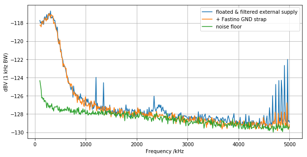
I've taken a quick look at the 100 kHz to 5 MHz noise spectum. I configured Kasli and Fastino as described in #56. Using the same spectrum-analyser configuration as in #56, I observed no spurs on channels 24-31. This measurement was taken with the DACs set to 9.5 V. No DAC updates were written during the measurement. |
|
To check I understand the implications of this, you're essentially reproducing the measurements in this trace https://user-images.githubusercontent.com/14295481/74259599-0f40fa00-4cf0-11ea-98ca-e73e4075b4f2.png and find the same results (which is expected since v1.1 implements the fixes that you'd manually implemented before). Is that right? Also, you expect this range of channels to be representative of all channels (or a worst case?)? i.e. so this shows that there are no spurs on Fastino that aren't related to Kasli SMPSs/grounding or digital updates? |
Indeed. Though without the high frequency features as they were environmental.
Previously, significant spurs were seen in these channels. I have no reason to expect them to be much better or worse for non-digital cross-talk.
That would be my interpretation. It is possible spurs are seen in other grounding configurations. I've certainly seen Kasli-SMPS-like spurs without trying. |
Digital crosstalkI've spot-checked some channels for digital cross-talk. I'm updating a single channel at the 2.55 MS/s. The channel is repeatedly written to -9.5 V (where -10 V would be the 0x0000 word). It is worth noting that the board I'm testing has the parallel termination populated. #62 suggests that the parallel termination is responsible for digital cross-talk to nearby DACs. This might be improved by desolating the parallel termination/using the variant that has the parallel termination de-populated. Spur intensities are given in dBmV of the spur peak. The analyser noise floor is -90 dBmV. Channels picked for location on board and their trace routingWith the selected channel updating, all other channels were checked for a 2.55 MS/s spur. From Channel 21 updates: no spurs seen
The spur seen in channel 8 is concerning. At a quick glance, the channel 28 trace routing around channel 8 is identical to channels 11, 14, etc. However, no spurs are seen in these channels. I will need to look at this more carefully. Channel 4 (comparison to #62)I only measured channels 0-15 for ch4 updates as this contains all previously observed spurs for channel 4 and the related digital traces are well away from channels 16-32
This is significantly improved on V1.0 ConclusionWith the new layout, there seems to be less cross-talk to channels. The strongest spurs I fund during spot-checks are much weaker than those previously seen. However, I found a significant spur. This seems worth investigating further. It may be worth repeating these measurements with the parallel termination removed. |
|
On further investigation, there is a major digital cross-talk issue with channel 8. Details are presented in #76. Essentially this renders channel 8 very susceptible to digital cross-talk. Other channels appear to be effected to a lesser degree. |
|
Thanks @pathfinder49 Could you clarify a few things here to make sure I understand correctly:
|


|
One other question: if we discount the channels that are near the termination resistors, am I right in thinking that the worst-case digital spur you measured was ~-80dBmV (100nV RMS / -157dBFs) at 2.55MHz (so should be easy to get another factor of ~10-100 from the trap filters) and that you believe (but haven't verified) that this is due to return currents from the parallel termination at the DAC? Obviously it would be nice to eliminate that by removing the parallel termination resistor (assuming that neither SI or issues around the series termination emissions prevent it), but I'd be okay living with that if we have to. If we decide to remove the series termination resistors, we should repeat this measurement to verify that the spurs don't get significantly worse (due to the fact that the series resistors were attenuating the high-frequency components of the digital lines) |
|
To confirm my interpretation that the -80 dBmV spurs seen in adjacent channels are due to the parallel termination, I desoldered the parallel termination capacitors of channel 28 and channel 4 and measured the effect on the spurs. Removing the parallel termination of channel 4 does indeed remove the -79 dBmV spur seen in channel 6. This also matches the V1.0 measurements presented in #62. Removing the parallel termination of channel 28 does NOT influence the -80 dBmV spur seen in channel 30. This suggests that the parallel termination is the cause of some (but not all) -80 dBmV spurs in adjacent channels. Given the difficulties arising from the series termination (#76), it is worth revisiting if we want to use series or parallel termination. |
The channel 4 measurments should be directly comparable to the measurements for channel 4 in #62.
Indeed. There are two 1.1 variants. (One with and one without the parallel termination capacitors populated.) |
|
@pathfinder49 I think we've now done all the testing we planned on this revision, haven't we. Shall we close this? |
|
Actually, no, let's keep this open until we've made a decision about termination for the digital lines and done some SI spot checks with a low capacitance probe. |
|
TLDR: The digital SI seems fine. I've looked at the digital SI with only one channel receiving digital updates. The channel update rate was 2.55 MHz. I used a 1pF, 1Ghz active scope probe for the measurements. Ideally, I would have liked to include clock jitter in this measurement by triggering off the CLK. However, I have no good way to get two high-speed probes onto the board simultaneously. The markers in the plot represent the DAC logic thresholds. Series terminationI measured SI with series termination on CH27 (ch28 in altium) as this has the longest digital traces. These traces are with 30 - 60 s peristance. Parallel termination capacitors were removed for this measurement.
Parallel terminationI measured SI with series termination on CH30 (ch31 in altium). This channel also has a long digital trace. The series termination resistors were replaced with a short circuit for this measurement.
|


|
@pathfinder49 thanks for performing those measurements. Am I right in thinking:
So, it sounds like the conclusion (pending checks on a few other channels) is that the series termination works really nicely and gives a better SFDR so long as we can sort out the placement/routing of the termination resistors and associated traces + vias. Is that all correct? |
|
After discussion, @hartytp and I agree that these points are not of concern.
|

|
We've completed our testing of v1.1. |
I've finally got my hands on a V1.1 board and am running it through some rudamentary tests.
Output Voltages
I've hooked up Fastino to an IDC-BNC adapter board. I then wrote all DAC channels to +9.5 V and measured the output voltages using a DMM (10 mV precision). All Channels read 9.5 V within the DMM precision.
Power rails
I measured the rail volatges on the test points using a DMM.
The text was updated successfully, but these errors were encountered: