Home
My article about how to make a wireless mouse/joystick for Amiga500 retro computer is published in Skrolli magazine (Issue 4 / 2017). This page provides additional material of more or less successful designs of retro / DIY wireless controllers that I have created so far. The contents require some understanding of basic electronics, embedded systems and the C programming language.
The original idea was to demonstrate a simple design for wireless controller, for example digital Atari type joystick, based on the XBee wireless radios. XBee radios feature a set of I/O pins that can be programmed to automatically detect a change in the pin state (i.e. high / low) and transmit the state over the network to a receiver radio, that then copies the state to an corresponding output pin. This is called Line passing that is available only for XBee model S2C radios (AFAIK).
Now, it is only needed to connect the joystick connector (typically 9pin D-Sub) output pins as inputs for a transmitter radio. In the receiving side, just connect the corresponding radio output pins into the Amiga500 joystick port. So, this design is rather simple as no programming or microcontroller needed, just create the PCBs and configure the radios for line passing. Line passing with XBee radios has been used previously with DIY joysticks, but the magazine article shows how to use this feature easily with existing Amiga controllers, such as beloved TAC-2.
See the video of the latest model, which details are explained below.
Pictured is a wireless DIY joystick for Amiga with two independent buttons, based on the transmitter design below.

The selected components used in the prototypes below are based on whatever suitable components the local electronics store has in stock and whatever default values the datasheets suggest. Thus the designs could be improved.
The DB9 joystick connector pinout varies slightly between retro computers. For example the pin 5, unused with Amiga, is used as a button with Atari ST.
Concerning the used level converters (5V <-> 3.3V) a simple transistor based BOB-12009 was selected that uses very little amount of power. Of course, some other ICs for example in the 74-series are suitable as level converters, but require additional control lines and consume significantly more power (e.g. around 20mA).
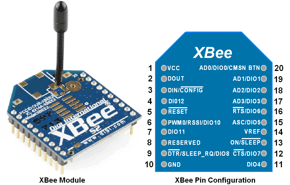
The generic XBee pinout, that is utilized throughout this document, is shown here.
The PCB schematics and layouts are created with Fritzing.
Please note: As discussed in the Skrolli article, that the design does not work very well with mouses due to required I/O pin sampling rate, but with joysticks the design works well. See test data at the bottom of this page. For smooth movement of Amiga mouses, sampling rate above 300Hz is required of which the XBee radios seem to be uncapable of.
Transmitter prototype connected to retro Tac-2 joystick.

The transmitter basically connects a joystick through male DB9 connector to the XBee radio. One pin mapping for Amiga computers is shown below, but the joystick lines can be generally connected to any XBee I/O pins. The joystick pinout may be slightly different for different retro computers.

Amiga joysticks utilize 5V voltage, when DIY joysticks can use any voltage available. The XBee radio operates with 3.3V. Therefore, two 4-channel level converters are utilized in the PCB to connect the six lines with different voltages of the radio and joystick. For this the board needs 5V and 3.3V regulators when assuming 9V battery as the power supply. With a battery operated device, a power switch is of course useful..

The files for this design can be found in this repository in the directory transmitter.
Receiver attached to Amiga 500.

The following pin mappings are used to connect the XBee output pins into the Amiga 500 controller ports (CN1 or CN2). Note that other Atari-type joysticks may use slightly different pinout.

Female DB9 connector connects the board to the Amiga ports, which also provide power for the board. Maximum output is 50mA, which is quite enough for the XBee radio that uses ~30mA for receiving. CN port voltage is 5V, therefore a 3.3V regulator is needed for the radio and the other side of BOB-12009 level converters.

The files for this design can be found in the directory receiver.
Ok.. so why stop with digital joysticks? Using a microcontroller (MCU) enables to use analog DIY joysticks with the good old Amiga 500 and provides a platform for additional features. More of that later..
Analog joysticks output the angle of the stick with changing voltage along the x- and y-axes. For example, the maximum left angle corresponds to VCC and maximum right angle corresponds to ground. Often, analog joysticks contain potentiometers that can be used to modify the voltages, i.e. modify the joystick sensitivity. The job of the MCU is to sample the voltages of the x- and y-axis with AD converter (ADC) and convert the numbers representing voltages into digital signals up, down, left, right. Now, two ADC channels are needed, one for each axis.
This design is based on ATtiny841 MCU, due to small size (as a SMD component) and for having just enough I/O pins. ATTiny841 has integrated 10-bit ADC, but for simplicity 8-bit scale is used for the voltage representation. Below are shown the schematics for a analog joystick board that uses the ATtiny841.

ATTiny841 pinout can be seen here. MCU uses its internal clock (1MHz) for operation, thus no external clock is considered nor MCU fuses need to be modified. To connect the radio to the MCU, following pins are connected.
- Lines PA5-PA2 (pins 8-11) provide the joystick position digital signal to the radio.
- ADC and XBee radio require a reference voltage for sampling the inputs that is provided through pins AREF (MCU pin 13) / VREF (XBee pin 14).
- Power and RESET pins are provided for the MCU (1 and 4) and radio (pin 1).
To connect an analog joystick, such as common thumb joystick, to the board you need to connect 5 pins: VCC, ground, X-axis, Y-axis and button. The connector "joystick" connects the pins followingly:
- Button (the upmost pin) directly to the radio input pin (DIO5) that is designated as the button 1 pin for the joystick.
- Next two pins are the position pins that are connected to the MCU I/O lines PA6 and PB2 (pins 5 and 7). the ADC channels are now 6 for y-axis and 8 for x-axis.
- Rest two pins provide VCC and ground for the joystick
The connector in the bottom is the power supply and programming interface for the MCU (to give a possibility for future improvements). This connector reuses some of the radio and MCU I/O pins for programming through MOSI (PA6), MISO (PA5 / DIO1), SCK (PA4 / DIO2) and RESET pins. Also it provides serial output through line TXD0 (pin 12) for debugging purposes.
The images below show a working prototype. (Yes, it's rather ugly but actually fits well in my hand..) Thumb joystick is connected through an off-the-shelf breakout board. In this prototype, power is provided by a button cell (CR2032), shown on the left side of the box. This solution could be better as this battery has only a small capacity, around 200mAh, and the battery can't be changed without opening the box.

The files for this design can be found in the directory analog-diy.
So, this model contains some extra features: autofire based on slide potentiometer and an OLED display to visualize the action! Hence the name ;-) Also, see the video

Due to ready-made OLED display drivers and graphics library, Arduino Pro mini (based on ATmega 328p) version 3.3V / 8MHz was selected as the MCU board.
The OLED display is based on SH1106 driver chip with five pins (DI, D0, RESET, DC and CS) and is simple to connect to any digital pins of the Arduino.
Autofire is based on a slider potentiometer that can be connected to any analog pin in the Arduino board. The Arduino program enables approximately 0-10 autofire rounds per second.
The illuminated button requires higher voltage to power up the led, up to 12V. In the design, a 9V battery is assumed as the power supply and connected directly to the led, which gives about 8.4V. The actual button voltage can be the anything, e.g. 3.3V as the VCC.
Otherwise, the joystick output pins and button pin are set by default in the high state through pull-up resistors.

The Arduino program code should be fairly straightforward to use. It seems that the display driver consumes most of the Arduino Pro memory.
Autofire and button outputs are read by the program that controls the state of the XBee radio button pin. This way the different controls are connected to the same output pin.
The files for this design can be found in the directory luxus.
The prototypes were tested indoors at a distance of ~5 meters. The image shows an oscilloscope capture with Tac-2 joystick. Signal A1 is from the transmitter side and signal A2 at the receiver side. Basically with joystick there is no lag, only a delay of couple of milliseconds.

Low-power wireless communications in the ISM band (2.4GHz) are not perfect in the real world and suffer from interference and obstacles such as walls inside buildings. Anyway, Digi promises over a kilometer line-of-sight range for XBee S2C radios.. ;-)
Autofire is quite handy for example in Xenon 2 Megablast ;-D
