Resetting the whole library #31
Comments
|
My suspicion would be that this is caused by an unstable local oscillator. You are right that a similar issue was described #27 in the past. However I was never able to reproduce it at all. Without any means to reproduce it I have no way to locate the issue and fix it. I suggest that you first try to tell the library that your oscillator might be unstable, e.g. set has_stable_ambient_temperature to false. Line 123 in 1103b38 If this fixes the problem tell me about it. If this does not fix the problem I have no idea what is wrong. If you really need to enforce a reset of the libary this is in fact done by calling Most probably I would need someone who can reproduce the issue and who lives close enough me such that I could visit and instrument the hardware with suitable measurement equipment. |
|
Thanks for your reply. |
|
I've done some more testing on two different hardwares: Board 1: Arduino clone (but definitly quartz crystal based) For all tests I used two different "Reichelt modules" and following time as a reference: https://www.uhrzeit.org/atomuhr.php 1st test: has_stable_ambient_temperature = false (as you suggested) 2nd test: has_stable_ambient_temperature = true 3rd test: has_stable_ambient_temperature = true My modest opinion: Test three shows the typical behaviour I mean. Board one shows large clock deviation and board 2 wrong date. Maybe this way it's possible for you to reproduce the problem ! To finish with something different: Thanks and best regards, |
|
Can you record some trace with the "Swiss Army Debug Helper" in mode Dm ? At least enough to reproduce the issue + some more hours? With regards to the simulation of bad reception: I tried several things in the past. E.g. the standalone debug helper. So far I found no way to reliably simulate real word noise. I know that in theory a lot of the noise can be modelled, but reality is still different. Without real world data I have no chance. The only thing that I can say for sure that I can not reproduce the issue with my setup. And I tried quite a lot of things (e.g. putting the antenna on top of magnetic loudspeakers or on top of motors). Sometimes I just pulled the antenna for some hours. The issue is that this approach is very time consuming and I can not reproduce the behaviour so far. |
|
Okay, I'll try to post a log to analyze the behaviour. Regarding to reset the whole library: |
|
Good point. Yes, this is a good idea. Maybe I should add it as already suggested in issue #30. Well, maybe if it hits the third time ;) |
|
Please find a first LOG attached (this is just to give you a start). BTW the procedure for this log (and the followings) is always the same. First I put the antenna in an optimal position, then I wait for the best clock_state possible (synced) and then I put the antenna in a "non-optimal" position ... I'm currently running further tests (both on AVR and ARM board), so hopefully I can provide a more significant LOG soon ... |
|
Just a short intermediate result: Furtermore there are two more questions:
|
|
I do not have an STM board to verify. However the code looks sound. With regards to log file I create a little analysis helper here. It detected no anomaly. Then I looked at it with the standalone debug helper Conclusion: it was synced for just 6 seconds and then the signal degraded. I have two possible explanations.
That is for (2) there must have been some correlation of the noise with the filter kernel. This could be "easily" fixed by more advanced signal processing. The issue is that my main target platform (Atmega328 aka Arduino) has so little memory and CPU. With other words: I know how to do this on bigger and better machines but given the tiny resources I have not yet found any really good solution for this challenge. Is the noise that you pick up real world relevant or is it just artifically introduced fading by turning the antenna? Where are you located? Is this issue really relevant in practice? What I am aiming at: my decoder is of statistical nature. As the noise level increases I have only two options: I opted for (2) because I did not want to implement an arbitrary limit. If you figure out that this is unacceptable in your situation then (1) would also fail to deliver any reasonable time. Now if you want to detect if (2) picks up questionable data I suggest to implement a simple check if time starts to jump backwards or if the decoded time drifts way to much relative to the local clock. I suggest to double check before that the local clock is definitely within the 100 ppm design limit. |
|
Thanks for your analysis. Regarding to double check the local clock 100 ppm design limit. I don't have the possibility to accurate measure the quartz crystal frequency but how about following idea: |
|
No we are not close at all. Please ignore this comment |
|
Just send me your phone number by private mail. Maybe we can have a call during the weekend. With regard to the issue, you say you use systick. Thus I assume you are running on ARM. On Saturday I will setup a test with an ARM board for 24h and see if there are any regressions. With my board I had never any issues so far as the signal quality around here is way above the limit for my library. So either there is some regression that did not catch my attention or there is something with your setup. 100 ppm should be absolutely OK, but there may be other issues. I suggest to discuss this by phone (or in person). |
|
So far my tests show nothing unusual. Maybe you could run the debug helper in mode DA to see if your clock is really stable. Sometimes it is not the hardware but interrupts that mess up the timing. |
|
After 48 hours on Arduino Due (ARM) with a Pollin Module everything looks perfectly well. I have to assume that it is something with your setup. The question is what? |
|
Sorry for my late reply. I was not at home the last days ... I could observe the drifting clock on both AVR and ARM based board. As suggested, I will run the debug helper in mode DA and report back. I'm quite busy until sunday but next week we can have a call if you like. @nameoftherose |
|
@lakeroe I live in Heraclion Crete (35.332832, 25.121835), 2000km from the DCF77 transmitter. I do not have your email. I am using this library on an UNO on breadboard. My problems were due to signal fading and too much noise (from power supply and the antenna). Since December 17 it is working reasonably reliably. |
|
Please find another LOG attached (in DA mode). |
|
What is the length of your antenna? |
|
I'm using this DCF77 module and the antenna is about 55mm long and 9mm diameter. |
|
This is a graph of the various performance metrics produced by swiss_army_debug_helper. |

|
Thanks for your analysis, you can clearly see the dependancy of the antenna orientation. How does your antenna look like ? |
|
I am using the Conrad module. Its antenna is 50mm. |
|
Looking at the analysis of nameoftherose there is very interesting behaviour. First sof all the phase lock fluctuates a lot. Then during the period with the poorest phase the month and day decoder "lock" to the noise. Once the signal gets really good (before 17:00) the other decoders increase in quality. However the mistakenly locked decoders start to converge to the proper value. Hence the quality decreases. The easiest way to fix this mess is to not allow the "slower" decoders to decode before the fast decoders are ready. That is: require that locks can only be acquired in the order phase, seconds, minutes, hours, days, months, years. I think this would fix it. There is a catch though. The current approach allows for significantly faster startup. I think I will fix it by introducing another configuration flag. What do you think about this proposal? With regards to using the weekday as some kind of checksum this will unfortunately not fix it. The reason is that if your signal quality is such that this issue happens then introducing this as a checksum will fix it for 6 out of 7 days of the week. The rest there will be still this issue. There is one more thing that I could do: I could introduce additional "flat out detection bins". The price to pay is 1-2 additional bytes of sram consumption per decoder. Thus about 12 additional bytes. This would also help to relieve this issues. Thus the action plan would be as follows:
What do you think about this approach? In particular about the choice of the default values? Should I default to maximum robustness (paying with more memory and slower initial sync) or should I default to the optimistic setup and require that people with extra poor reception need to adapt the configuration? |
|
@nameoftherose By the way: what did you use to plot the log statistics? |
|
@lakeroe If you send me your hardware then I also might be able to gain more insights. Did I understand it right that you are within <300 km from Frankfurt? One more question: why are you putting the antenna intentionally into a poor reception position? This is a very interesting approach but I would assume that the antenna is mounted in an optimal orientation and that the library will only have to tackle "other noise". What you are doing is basically raising the noise floor by more than 10d dB, maybe even 20 dB. This is great for testing but close to Frankfurt it is somewhat pointless. So I am wondering why you do this? BTW: together with the analysis of nameoftherose I think this finally shed some light on why some people reported issues with my library that I was not able to reproduce. Obviously your test approach is a good idea :) |
|
I analyzed the log and with the hints of the picture by nameoftherose the plot thinkens. Your decoder module is biased to all 1. Thus during periods of bad reception it shows a different behaviour than mine. Mine biases to 0. This also explains why I was never able to figure this out. My module is biased differently. I will fix the library. However I am very busy right now. I can not promise that I will be finished in June. This might take some weeks. |
|
The graph is created as follows:
|
|
@udoklein |
|
@udoklein *) I think your plan sounds promising and we should give it a try. *) Default values *) My hardware *) Distance from Frankfurt *) Antenna orientation *) Time schedule |
|
Well, I used a Pollin module for my tests --> in my location it is differently biased. As you say most probably I will gain no insights from your hardware. However you could do me a favour. Now that we know what is most likely the issue it would be nice if we can create a log file which will reproduce the issue with my standalone debug helper. Unfortunately the log file with the issue does not. The reason is that the log does not capture the full information prior to the first sync. There would be two options:
According to the theory (2) should still reproduce the error but it should also capture enough signal such that the standalone debug helper will also recreate the issue. This would help me a lot during testing. Would this be possible for you? I am not in a hurry. If this takes 2 or 3 weeks it would still be in time for testing. |
|
@udoklein how does the adjustment value (printed by the Swiss_Army_Debug_Helper in mode Da) relates to crystal accuracy/stability; |
|
Because KST was always a little bit on the slow side when plotting I created an IPythone notebook to speed up the processing of the log files. You can find it here. |
|
Here are the first 4 plots I generated from lakeroes logs:
|


|
@nameoftherose what is acceptable and what not is determined by the datasheet of the crystal. Usually I observe adjustments in the range of +/- 50 ppm or less. Thus 40 ppm is OK. However the algorithm assumes that the crystal is stable. Stability is not checked or tuned by the algorithm. Thus this value gives no indication if it is stable or not. If you signal quality is somewhat reasonable you can check stability also in mode Ds by visual inspection. If you scrool through the log file and the signal drifts at a more or less constant rate, then the crystal is stable. If the rate is not almost constant then the crystal is unstable. |
|
@udoklein thank you. |
|
@udoklein Regarding the plots you've created from my logs: How do you interpret them ? Is your library working as expected ? |
|
Looking at the plots the library works as expected. However I also see that I need more sophisticated analysis tools to gain deeper insights. This may take some time. |
|
Due to my poor oscillator long term accuracy I did another test. Then I repeated my test from further above. This time the clock was off by about 3 seconds after 86 hours which equals to about 10 ppm. This is an improvement by a factor of 5 and I hope this also leads to an improved and more stable short term accuracy. Using this change I started further dcf77 receive tests with different antenna positions. 1. conservative_minute_quality 21.07.2018 09:55h Start, antenna horizontal and rotated by 90 degrees towards Frankfurt (best position) -> No matter how I orientate the antenna, the time is ALWAYS accurate !!! LOG-File: dcf_2018-07-21_ARM.zip 2. aggressive_minute_quality (old behavior) 23.07.2018 20:48h Start, antenna horizontal and rotated by 90 degrees towards Frankfurt (best position) LOG-File: dcf_2018-07-23_ARM.zip -> Time is still drifting and also decoded wrong Conclusion: |
|
@lakeroe now that you have a known accuracy crystal, will you please tell me what the output of frequency analysis command |
|
According to another test I have to revise my opinion. Even with paranoid_minute_quality I get wrong date/time. 1. conservative_minute_quality 24.07.2018 20:20h Start, antenna horizontal and rotated by 90 degrees towards Frankfurt (best position) 2. paranoid_minute_quality 25.07.2018 16:30h Start, antenna horizontal and rotated by 90 degrees towards Frankfurt (best position) @nameoftherose confirmed_precision ?? adjustment, deviation, elapsed Does this answer your question ? |
|
@lakeroe yes thank you! Never mind the UNO. |
|
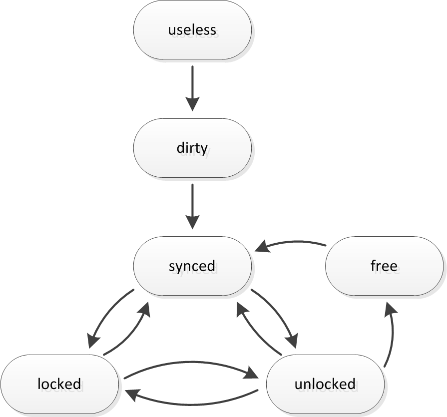
@nameoftherose The state engine is implemented in However it is possible to transition from synced to useless by calling the setup method after the clock has synced. |
|
@lakeroe: I was on vacation so I did not follow this thread closely. What is your current state of affairs? Does the library work as expected in the good position or does it fail also in the good position? |
|
In file dcf_2018-07-23_ARM.zip line 17406 a direct transition |
|
You refer to this: This is indeed interesting but admissible. Have a look at https://github.com/udoklein/dcf77/blob/master/dcf77.h#L1570 That is the state engine will transition from synced to unlocked and then immediately transition from unlocked to free. This happens during one cycle. You can argue if this is a direct transition or not. The explanation is as follows: the phase quality gets very low and the algorithm can not determine anymore if it just lost the phase or if it was already out of phase. The point is that tries dead reckoning of the phase in state "unlocked". If this is not possible then it has to default to free. What does this imply? In state "unlocked" it can leverage the knowledge of the approximate time to still reliably synthesize the target signal that making it slightly easier to reaquire the signal. If this is not the case then it will more or less "cold start". It can be argued if there is a better way for the transition from synced to unlocked to decrease the likelyhood that it defaults to free. This is a very tricky question and in my opinion not really worth the effort for optimization. I could be done though. |
|
@udoklein thank you. |
|
Yesterday was to hot in Germany. I should have spotted this on my own. You are of course right. I think this should be handled in a separate issue (#34). |
|
@nameoftherose Thanks a lot for noticing this one. I fixed it by now :) |
|
@udoklein , I should have also spotted that this was caused by the uninitialized |
|
@udoklein confirmed_precision ?? adjustment, deviation, elapsed before it showed confirmed_precision ?? adjustment, deviation, elapsed LOG-file: dcf_2018-08-08_ARM.zip So I can't really be satisfied. |
|
1 ppm = one part per million = 1 / 1 000 000 = 1e-6 What you describe is a very clear indicator of a large clock drift. In my opinion your local oscillator is unstable. If you scroll through your file then you can even see (looking as the "scope" output) that your clock is stable for a while and then starts to drift with an excessively high rate. This looks a lot like a way out of spec oscillator. Unless you can bring up any really convincing argument why your oscillator is good I would say the oscillator is at fault with a probably >95%. If you do not have a frequency counter to check if the oscillator is good you could benchmark it with a second Arduino like this: https://blog.blinkenlight.net/experiments/measurements/crystal-deviations/ or like that https://blog.blinkenlight.net/experiments/measurements/crystal-deviations-2/. In my opinion this issue is a hardware issue and there will be no software fix for it at all. |
|
Because I've already tested an original Arduino Uno and a few different STM32F103C8T6 boards and they behaved all pretty much the same, I can hardly believe it's an oscillator problem. Do you think this explains anything ? Maybe you could also have a look at the changes I made to the library (they are marked by * lakeroe *) ... If this all does not help, are you interested in finding the root cause of the problem ? |
|
The Uno is officially not supported because it does not feature a crystal oscillator for the controller. The STM32 is not officially supported. The point is that for officially supported hardware I got only onece a similar issue and this was caused by the oscillator. Notice that the (in)stability of the crystal oscillator is not only affected by the crystal but also by other parts, in particular the load capacitors. With cheap boards the oscillator design might be suboptimal. If you want me to analyze the issue please send me a board + programming adapter. My standard policy is to NOT return boards I get sent for testing. In particular if they are not officially supported. If this is OK for you, send me the hardware. Otherwise I highly recommend to get a frequency counter and check the hardware. |
|
@lakeroe , do you have a commercial dcf clock? How does it perform relative to the board? Can you experiment with an officially supported board? |
|
For now I will not do any further testing, but maybe I will check my local oscillator in the future. Anyway, thanks for your comments and help so far ... |
Hello,
I'm running the library on an ARM STM32F103C8T6 and this works very well, but now I've noticed a strange behaviour.
After power-on the first received time if (clock_state >= Clock::free) is always valid and accurate but after some hours (or days) the time starts to drift away and sometimes also the date is wrong allthough the inaccuracy should be below 200 ms according to the comment in dcf77.h. This seems to happen especially in a quite noisy environment.
I assume this problem is related to: #27
Because I use this library to synchronize my ARM built-in realtime-clock I need a reliable time only once in a while. So my idea is to reset the library everytime a valid time is received (clock_state >= Clock::free).
My C++ knowledge is quite limited but I've managed to add a reset-function which calls DCF77_Clock::setup() and DCF77_Local_Clock::setup() and I call this reset-function everytime a valid time is received.
I'm currently running a test for about 24h and this seems to work well.
Do you think this is the right approach for my problem and is the reset-function correctly implemented ?
Thanks and best regards,
lakeroe
The text was updated successfully, but these errors were encountered: