Navigation
-
3.1 Base State
3.2 Waypoint State
3.4 Search State
3.6 Gate State
-
Driver, FailureZones, and PathPlanner
4.1 Driver
4.2 FailureZones
4.3 Path Planner
-
Context, Rover, Environment, Course
5.1 Context
5.2 Rover
5.3 Environment
5.4 Course

Note: State machine diagrams are generated using the state machine visualizer tool Note 2: It may seem like we have "duplicate" arrows in this diagram. This is not a bug in the visualizer. We sometimes have two separate transitions that are representing the same state change. This is done to express the reason behind the state change more cleanly.
run: rosrun mrover visualizer.py in order to have live visualization of what's going on in the state machine.
A state is an object that defines a certain mode of behavior for a system. We can define a state through its behavior and also its transitions. For our purposes, the Navigation system can be "in" exactly one state at any given time. Every time one cycle of the system occurs, we execute the logic of the current state, and then at the end of that execution, we transition into a new state. This new state does not need to be a different state (in fact, most of the time the "new" state is just the same state). In this system, we can create complex behavior in an organized and relatively easy-to-think-about manner. Many times, state machines are created "manually" through code that looks something like this:
switch (state) {
    case StateOne:
       action()
       if action_complete:
           state = StateTwo
       else if action_failed:
           state = StateThree
       else:
           state = StateOne
       break
    case StateTwo:
       print("complete")
       state = StateTwo
       break
    case StateThree:
      print("failed :(")
      state = StateThree
      break
}
This is probably fine in simple cases such as the one above but when state machines get big and complicated the logic can very quickly get hairy and hard to debug. The solution to this is to rethink what a state really is on a more fundamental level: an object. Every state in a given state machine shares many properties. Every state has some action that gets run and every state can transition into other states. If we implemented each state as an object that inherits from some base class with a function that runs the action and returns some transition, we can then map those transitions to output states and implement that actual logic for putting together the state machine itself just once. In other words, we create the abstraction of states just once for any general state machine, and then we can put together an arbitrarily large state machine just by thinking of it one state at a time. Smach is a library that already does this. It makes defining states easy and handles the creation and execution of the actual state machine all under the hood. We would highly recommend reading the smach documentation or looking through some smach example code in the link above to understand the smach state interface.
The Base State is a custom parent class created to more cleanly handle the termination of states. When developing states be sure to inherit from Base State and override evaluate() instead of execute(). Execute() has been defined within BaseState to call evaluate() and has logic to stop state machine execution if the software is terminated early.
Base State also contains logic to return the transition "off" if a disable has been requested by the GUI. All states that inherit from base state will therefore not need to worry about implementing the switch to off state as all states by default have the logic and they also have the transition by default.
Off State is the default state of the state machine and it indicates that the navigation system is currently off. It does nothing. Importantly, it does NOT send out zero velocity commands as those would overlap with valid velocity commands from teleop. We switch out of the Off State and into the Waypoint State if we receive a request to enable auton which can be inferred from the course object being not None.
Done state may seem similar to the off state but it is not the same. We switch into the Done State when we have completed the objective provided by teleop GUI or after we have given up on that objective. We send out zero velocity commands in this state because the rover is still enabled and we don't want it to move even under teleop controls until it is disabled. However we will switch back into waypoint state if we receive a new course in this time. The meaning of this is that we technically do not have to turn auton off (from the gui) in order to start a new objective.
Summary: The Waypoint State (inherited from Base State) was created to command the rover along a course of waypoints.
Actions (Published messages): The Waypoint state publishes drive commands (Twist messages) that are calculated via the get_drive_command function. It will use the waypoint_indexth waypoint in the course as input to the get_drive_command function and if the get_drive_command function returns true, we have reached the current waypoint so we then increment the waypoint_index variable.
Transitions:
- If the waypoint at
waypoint_indexis None: transition into the done state - If we see an AR tag (via a message from perception): Transition into the Approach Post state
- If we complete a waypoint with an attached AR Tag ID: Transition into Approach Post state (IN DEVELOPMENT: transition into search state)
- Else: Stay in Waypoint State
Summary: The Approach Post State (inherited from Base State) was created to command the rover towards a spotted fiducial target (AR tag).
Actions (Published messages): The Approach Post state publishes drive commands (Twist messages) that are calculated via the get_drive_command function. It uses the position of the spotted AR tag as the position input to the get_drive_command function and if the function returns true, we have reached the AR tag so we exit the state.
Transitions:
- If fiducial tag position is None: Return to Search State
- If we have arrived at the AR Tag: Return WaypointTraverse
- Else stay in Approach Post State
Summary: The search state makes the rover follow a spiral search pattern around its starting point in search of either an AR tag or a gate. Once it sees what it's looking for, it switches into the Approach Post State. See the documentation below to see more info regarding the Trajectory class and SearchTrajectory class for more info regarding the exact mechanics of a trajectory and the specific search trajectory.
Actions (Published messages): The Search state publishes drive commands (Twist messages) that are calculated via the get_drive_command function. It uses the position of the next point in the search pattern as the position input to the get_drive_command function and if the function returns true we have reached the next point in the search pattern so we increment our path index. Once the path index is equal to the length of the path, we have traversed the entire search pattern and just give up (maybe we don't have to do this)
Transitions:
- If we have seen the gate: return Gate Traverse state
- If we have seen a post during post search: return Approach Post state
- If we have seen a post during gate search: return Partial Gate state
- If we have finished all the points in the trajectory: return Done state
- Else stay in Search
Summary: The Partial Gate State allows the rover to search for the second post of a gate when it has already found one of the associated posts.
Actions (Published messages): Publishes drive commands (Twist messages) that are calculated via the get_drive_command function. It uses the position of the next point in the search pattern as the position input to the get_drive_command function and if the function returns true we have reached the next point in the search pattern so we increment our path index. Once the path index is equal to the length of the path, we have traversed the entire search pattern and just give up (maybe we don't have to do this).
INCLUDE DIAGRAM OF PATH HERE
Transitions:
- If fiducial position is None: return to Search state
- If a gate is found: return Gate Traverse state
- If second post is not yet found along path: return Partial Gate state
- If path is completed, but second post is not found: return Done state (maybe change)
Summary: The Gate state allows the rover to traverse through the gate. It is active when the rover has an estimate regarding the gate's position (via the gate object in the context being not None). See the documentation below regarding the Gate class, Trajectory Class, and GateTrajectory class for more info regarding the exact mechanics of how these structures work. This section is just regarding the high-level logic of how the gate state works.
Actions (Published messages): The Gate state publishes drive commands (Twist messages) that are calculated via the get_drive_command function. It uses the position of the next point in the gate trajectory as the position input to the get_drive_command function and if the function returns true we have reached the next point in the gate trajectory so we increment our path index. Once the path index is equal to the length of the path, we have traversed the entire gate path so we go into the Done state.
Transitions:
- If we have finished all the points in the Trajectory: return done
- Else stay in Gate
The DriveController class maintains necessary state for driving the rover to a target. It was originally implemented as a pure function, however, we found that certain desired enhancements made maintaining state necessary.
The caller only needs to call two functions:
get_drive_command(target_pos, rover_pose, completion_thresh, turn_in_place_thresh, in_odom, drive_back) -> Tuple[Twist, bool]
This function returns a tuple of a Twist message and a boolean representing the necessary drive output and a completion status for driving the rover to a POINT (not a pose, i.e no rotation) given the rover's POSE (includes position and rotation). The completion thresh is a distance representing how close the rover needs to be to the target in TF units to consider itself done. The turn in place thresh represents an angle below which the rover will try to drive straight to the target and above which the rover will try to turn towards it. The in_odom and drive_back parameters are booleans representing whether we are moving in the odom frame and driving backwards respectively. See the below algorithm section to see how this function works.
reset()
This function resets the state variables listed below to their initial values.
-
last_angular_error (Optional[float])represents the angular error that was recorded at the most recent call to the get_drive_command function. It is initialized as None -
driver_state (DriveMode)is an enum that is either DriveMode.STOPPED, DriveMode.TURN_IN_PLACE, or DriveMode.DRIVE_STRAIGHT. It is initialized as None.
The get_drive_command function is used by many states and its job is to determine the Twist command to send the rover to a desired point. It automatically traverses to intermediate targets if the straight-line path to the ultimate target crosses through one or more FailureZones (see FailureZone and PathPlanner documentation below).
Its signature is as follows: def get_drive_command( self: DriveController, target_pos: np.ndarray, rover_pose: SE3, completion_thresh: float, turn_in_place_thresh: float, in_odom: bool = False, drive_back: bool = False, ) -> Tuple[Twist, bool]:
Inputs:
- The target position (a 3D position vector)
- The Rovers pose as an SE3 object
- A completion threshold (in meters)
- A turn-in place threshold (representing the minimum angle between the rover's direction and the vector towards the target position allowed before we begin driving straight and outside of which we turn in place)
- in_odom represents whether we are driving in the odom frame or not
- drive_back represents whether we are driving backwards or not.
Output:
- A Twist message containing the desired command velocities for the left and right sides of the drivetrain
- A boolean that is true if the drive is complete and false if it is not complete
Summary of [previous drive algorithm: The previous drive algorithm was quite simple. At a high level, we start by turning to face the (potentially intermediate) target point and then drive straight towards it. This is implemented via calculating first whether we are within the tolerance of facing towards the target (and if we are we add an x component to the output vector) and then calculating a corrective turning factor based on our angular offset from our current direction vector and the vector facing towards the target. This will result in us either driving towards the target while trying to correct for any angular errors if we are within the dot-product tolerance or just simply turning in place until we are within the dot-product tolerance.
However this basic algorithm is not quite enough to get the desired behavior in all cases. In testing we found that the rover tends to oscillate in some situations (namely - when we are driving in the odom frame) this is likely because of latency in the odom frame measurements. This latency is undesirable but some amount is unavoidable so we require workarounds to stop oscillations. The primary one that we settled on was using the intermediate value theorem (IVT). Basically, if the sign of our error changes, we know that we have passed through zero and can essentially just 'give up' right there. We use this for our angular error (which is where the oscillation was) if the sign of our angular error changes: we stop trying to turn in place (even if we are still outside the turn in place threshold).
This is the reason why the function was refactored into a class and the last angular error is maintained. But then why did we build a state machine? It seems like on a surface level this is not that hard of a change to make because we can just add an extra check to our existing logic for not turning anymore. However the problem comes when evaluating the logic for going from driving straight to turning in place. If we continue to use the previous logic of turning in place whenever the angular error is outside of the threshold you end up at exactly the same problem,the sequence of events is as follows: From iteration 1 to 2 you switch angular error signs and then use IVT to recognize that we have done so and start driving straight, the next iteration of the loop (iteration 3) the error is of the same sign as it was in the last one but still outside of turn_in_place_thresh thus we switch to turning in place and once again begin oscillating albeit this time with a iteration in between each swing. To prevent this, we can instead switch to turning_in_place only on the rising edge of the turning error. What this means is we only switch from driving straight to turning in place if the previous error was inside of the tolerance and the current error is outside of the tolerance, this prevents us from oscillating in the aforementioned case because in both cycle 2 and 3 we would have been outside of the tolerance and thus not hit the rising edge.
Here is a diagram showing various situations from time t to t+1 that are and are not rising edge triggers

All of this logic can be a bit dizzying, so we decided that it would be cleanest and easiest to understand if the drive code was refactored into a state machine. Below is a diagram of the state machine.
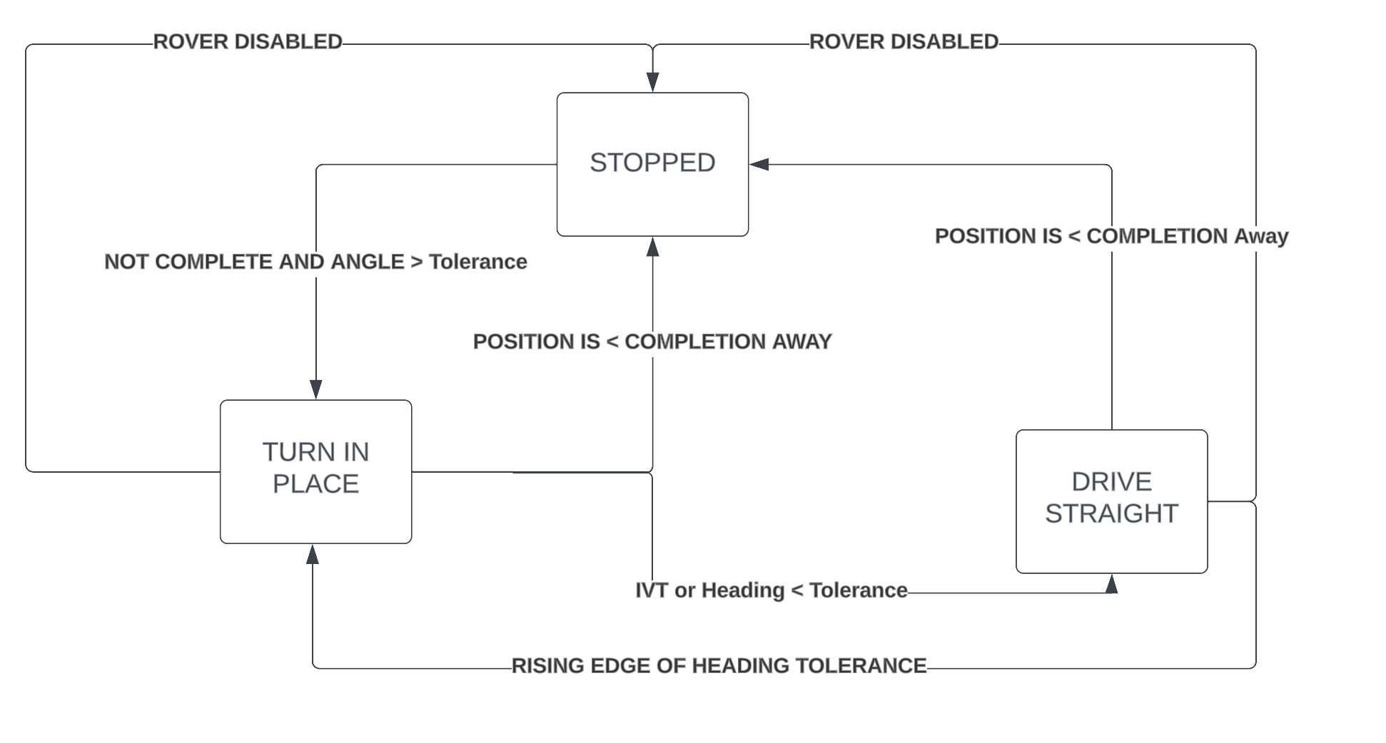
The logic in the code is written to follow the state machine diagram. At a high level the rover flows from being stopped until it has a target farther away then completion_distance to turning in place until it is either within angular tolerance or IVT, and then driving towards it until it arrives, with early escapes for arriving and disabling. The actual control logic remains as described above
Context is a class that holds many common functions and variables between the states. It serves as the bridge between the Navigation node and the other ROS nodes. The context class also holds references to an object of the Rover class as well as an object of the Environment class and Course class. The Rover class deals with all data related to the rover, the environment class deals with all data related to the environment surrounding the rover. See below for a list of important functions in the Context, Rover, Enviornment, and Course
-
course: Course object (see Course description) -
env: Environment object (see Environment description) -
rover: Rover object (see Rover description) -
driver: Driver object (see Driver description) -
disable_requested: boolean indicating that a disable has been requested and has not yet been processed
The course class keeps track of the rover's course. A course is essentially just a managed queue of waypoints that represent where the rover needs to drive. Each waypoint also maintains information regarding what Fiducial ID it is associated with as well as what the rover should do after reaching said waypoint (nothing, gate, post)
-
increment_waypoint()increments the saved waypoint index in the course that the rover is currently trying to follow -
waypoint_pose(wp_idx) -> SE3returns an SE3 pose object representing the pose of the waypoint at the specified index in the active course -
current_waypoint() -> Optional[Waypoint]returns the object (or none) of the current waypoint -
is_complete() -> Boolreturns True if the rovers waypoint index is past the number of waypoints in the course
The environment class keeps track of data regarding the environment around the rover.
-
get_fid_pos(fid_id, frame="odom") -> Optional[np.ndarray]returns the position (as a numpy array) of the tag with the given ID from the tf tree in the given frame (default to odom frame) or none if there is no tag with that id in the tf tree -
current_fid_pos() -> Optional[np.ndarray]returns the position of the fid associated with the current waypoint (or none) if we don't have one -
current_gate() -> Optional[Gate]returns a Gate object representing the current gate or none if we don't have one (see Gate class documentation for more info regarding Gate class)
The rover class keeps track of the interface regarding the rover itself
-
get_pose()->SE3returns the pose of the rover as an SE3 -
send_drive_command(Twist)sends a twist command to the rover -
send_drive_stop()tells the rover to stop
The Gate class represents the position of a gate. It just has two np arrays representing the position of post1 (the post which has the same ID as the waypoint) and post2 (the post with waypoint id + 1)
The Trajectory class is an abstract class that we use to represent a planned path that the rover takes. It is made up of a list of coordinates (still an np array) and maintains an internal pointer to the current point that the rover is on in the list. The base functions of getting the current point (get_cur_pt) and incrementing the point (increment_pt) are implemented in the base class itself. Below is the documentation regarding the two children of the Trajectory class, SearchTrajectory and GateTrajectory
The SearchTrajectory is a trajectory that is created to represent a search pattern for the rover. It has an additional property added to the class representing the fid_id that we are looking for as well as a list of directions indicating the order of the spiral. It will generate a list of coordinates representing target positions along a 2D square spiral emanating outwards from the waypoint using the following function. (this is copy-pasted directly from the code)
# First we will attempt to create the "delta" vectors that get added at each point
# in the spiral to get to the next.
deltas = np.tile(cls.dirs, (num_turns, 1))
# We will build the coefficients for the delta vecs now that we have the correct
# layout of unit vectors Given the distance parameter 'd', the coef layout we
# need is [d,d,2d,2d,3d,3d...]
dist_coefs = distance * np.repeat(np.arange(1, num_turns * 2 + 1), 2).reshape(-1, 1)
deltas *= dist_coefs
# At this point we use cumsum to create a new array of vectors where each vector
# is the sum of all the previous deltas up to that index in the old array. We
# also make sure to add the center coordinate in here too so the spiral is in
# the correct location
coordinates = np.cumsum(np.vstack((center, deltas)), axis=0)
return SearchTrajectory(
        np.hstack((coordinates, np.zeros(coordinates.shape[0]).reshape(-1, 1))), fid_id,
)
A GateTrajectory is a trajectory that is created to go through a gate. It is constructed through a classmethod "spider_gate_trajectory" which specifically generates coordinates using the spider traversal strategy (documented below). Because of the modular design of the Trajectory and GateTrajectory classes, if one wanted to employ a different strategy for driving through a gate, they would simply need to create a new class method that returns a GateTrajectory with different coordinates
The spider gate trajectory works using the following strategy. First, imagine the gate in 2D space.
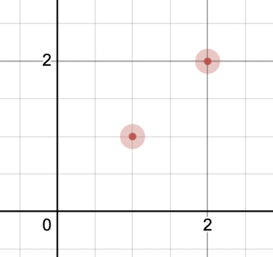
Now let's find the center of the gate by simply averaging the post positions
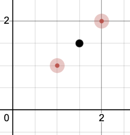
Now we will generate "approach" points the idea with an approach point is we want to go straight through the gate so we will generate points on the line that cut straight through the center of the gate a certain distance away from the gate (which we call the approach distance). The goal is to add points like this:
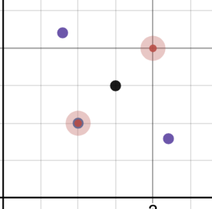
We calculate these points by first calculating the direction vector of the posts (post2 - post1). Then normalizing it and getting a vector perpendicular to it. Then the approach points are just going to be the center plus or minus that perpendicular direction vector scaled by the approach distance.
Now we might think that this is enough to traverse through the gate, we simply follow the approach points and we will go straight through! And this may be the case but in some cases, the path to the approach point will actually collide with the gate post itself and thus this doesn't always work. In order to create a path that does always work we need to add a few more points to our potential trajectory, preparation points.
We can calculate the preparation points similar to how we calculated the approach points. We use the same normalized perpendicular vector but this time scale it by twice the approach distance (so its farther away) and add and subtract it with each of the posts (thus resulting in four points)
Now we have a bunch of points that are plotted but clearly, we cannot put all of them in our path. We must select one preparation point, one approach point and one victory point (the victory point is what will actually drive the rover through the gate).
The key observation here is that if we choose the preparation point closest to the rover, we will never collide with a post. Then we simply choose the approach point closest to the selected prep point and then finally choose the other approach point as our victory point. And we're left with a three-point trajectory that will always take us through the gate with no possibility of colliding with the posts. Here is what one such trajectory may look like (in blue), we can figure out what the closest points are by finding the minimum norm of either the vector of the point minus the rover (distance to rover) or the point minus the selected prep point (distance to prep point):
Utilizing the spider_gate_trajectory coordinates given, gate_select_path returns the shortest path possible. The decision of selecting the path can be shown down below. Following the same 2D plane path shown above, the graph shows all the points that can be given:

The next image is an example of what the spider_gate_trajectory would return to us. This would the current path that the rover would take by going back to the preparation point, but this is inefficient so instead we pick the shortest path possible.

We make this decision by using the Shapely Library. The specific parts that we use in the Shapely library is shapes and lines. We make the gate posts a circle with a radius of 0.5 meters. The 0.5 allows us for clearance of the rover. Then we make paths starting with the shortest and then we find out if the path intersects with the circle shape made. The paths are made with the helper function make_shapely_path.
In this function we are given the points and create a line string by using the np function vstack. The function creates a line string that is compared and checked in the gate_select_path function.
The image below shows an example path being selected.

The paths that we make and select from go in the following order:
- Center, Victory
- Approach, Center, Victory
- Preparation, Approach, Center, Victory
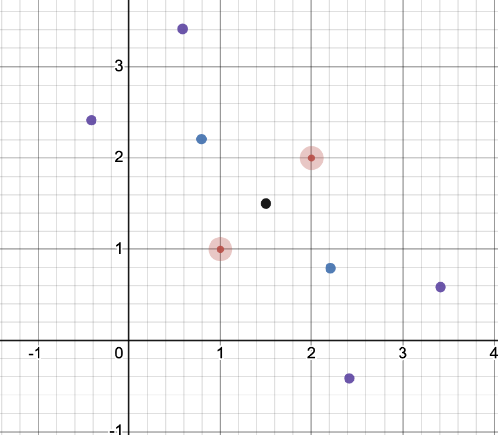
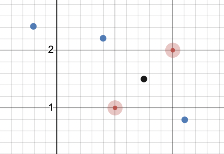
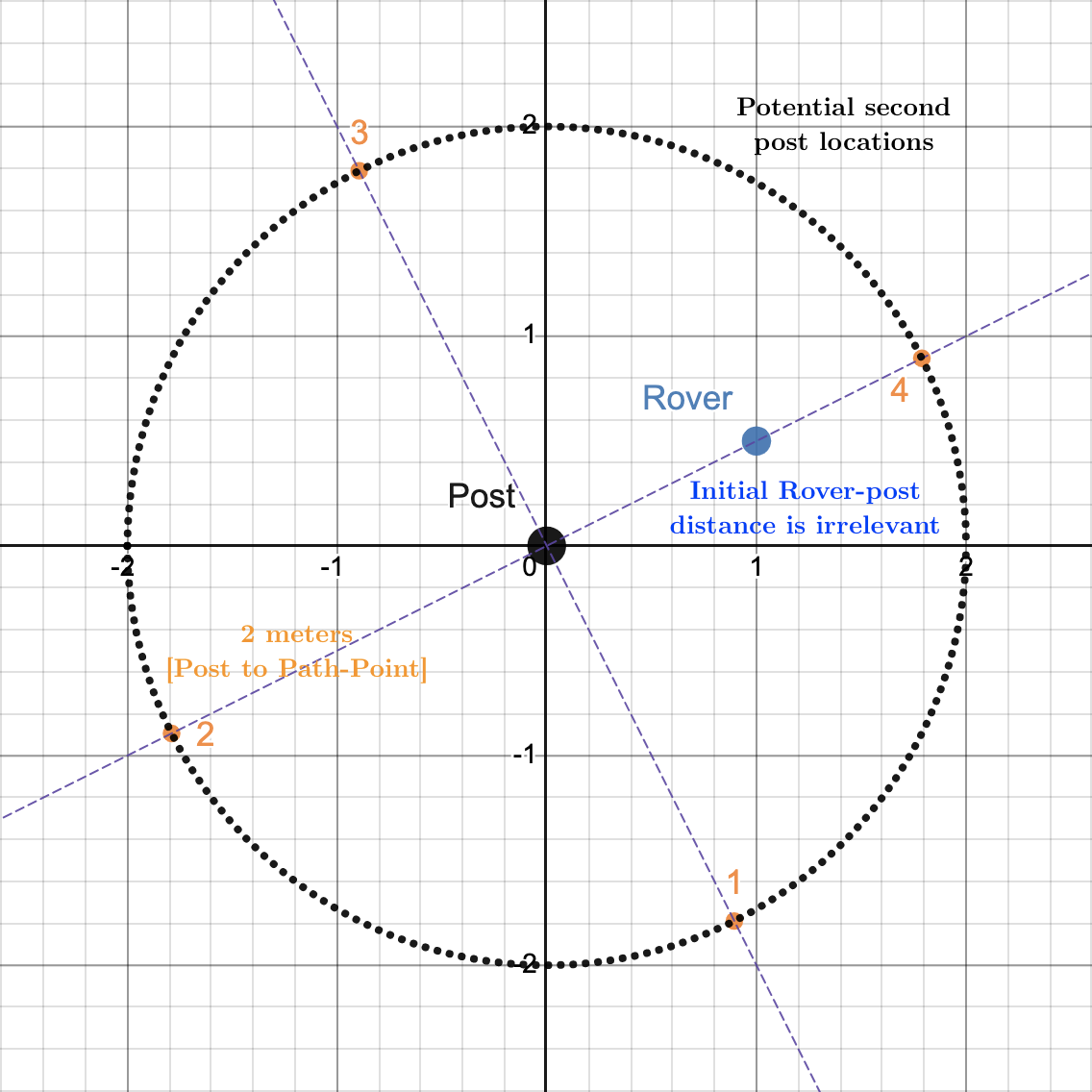
Once exactly one (but not both) of the AR tags that comprise a gate have been identified, the rover enters the PartialGate State. Posts are exactly two meters apart; the rover conducts a search around the identified post, traversing a square-shape that approximates a circle with a radius of two meters. In the diagram below, the Rover would go to Points 1, 2, 3, 4 in order. The second post must be somewhere on the dotted black circle; so, by traversing in a square shape (approximating a circle), we are bound to run into and detect the second post.
The Driver class is an attribute of Context and is used to determine Twist commands to send the rover to a desired point while keeping track of and avoiding failure zones (See FailureZone description below). The Driver also includes a PathPlanner class that helps avoid these failure zones. There are three important methods in this class:
The get_drive_command function is used by many states and its job is to determine the Twist command to send the rover to a desired point. It automatically traverses to intermediate targets if the straight-line path to the ultimate target crosses through one or more FailureZones (see FailureZone and PathPlanner documentation below).
Its signature is as follows: def get_drive_command(target_pos: np.ndarray, rover_pose: SE3, completion_thresh: float, turn_in_place_thresh: float) -> Tuple[Twist, bool]:
Inputs:
- The target position (a 3D position vector)
- The Rovers pose as an SE3 object
- A completion threshold (in meters)
- A turn-in place threshold (representing the minimum dot-product between the rover's direction and the vector towards the target position)
Output:
- A Twist message containing the desired command velocities for the left and right sides of the drivetrain
- A boolean that is true if the drive is complete and false if it is not complete
Summary of drive algorithm: The current drive algorithm is quite simple. At a high level, we start by turning to face the (potentially intermediate) target point and then drive straight towards it. This is implemented via calculating first whether we are within the tolerance of facing towards the target (and if we are we add an x component to the output vector) and then calculating a corrective turning factor based on our angular offset from our current direction vector and the vector facing towards the target. This will result in us either driving towards the target while trying to correct for any angular errors if we are within the dot-product tolerance or just simply turning in place until we are within the dot-product tolerance.
The add_failure_zone function adds a newly-detected failure zone to keep track of to the Driver's PathPlanner object. No output is returned.
Input:
- A
FailureZoneobject to be added
The add_post_as_failure_zone function implements functionality to add a FailureZone corresponding to the position of a post to the Driver in order to avoid crashing into the post.
Input:
- A numpy array representing the position of the post (typically retrieved from
self.context.env.current_fid_pos())
Failure zones are any area on the map that the rover should avoid in the future. They have a wide range of uses, from marking posts that the rover should not run into, to marking large areas where the rover should not go at all. Generally, the rover will drive on the edge of the failure zone, so failure zones should be created with some inherent padding. FailureZone objects can be added to the Driver as described above so that they are avoided in the future. A FailureZone is represented as a Polygon object (from the shapely library). FailureZone objects define the following methods:
-
intersects(line: LineString): Returns true if and only if the givenLineStringobject properly intersects (i.e. does not simply touch the boundary of) the underlyingPolygonof theFailureZone -
get_vertices(): Returns the four vertices of the axis-aligned bounding-box (AABB) that bounds this failure zone as a list of 4shapelyPointobjects. These vertices are returned in clockwise order, starting from the lower-left vertex. -
get_closest_vertex(point: Point): Returns the closest vertex to the given point as aPointobject.
In general, unless working to change the FailureZone avoidance algorithm, other services should only need to instantiate FailureZone objects using Polygon objects and pass them to the Driver.
The PathPlanner object implements the core logic for keeping track of and avoiding failure zones. A member of type PathPlanner is used by the Driver to calculate intermediate target points on track toward an ultimate target that will avoid driving through failure zones. The PathPlanner implements several functions that are used by the Driver:
Given a FailureZone object, this function adds it to the PathPlanner so that this failure zone is avoided in the future.
- Signature:
add_failure_zone(FailureZone fz) --> None
Given source and destination Point objects, returns the current intermediate target for the rover to drive to. This intermediate target is based on the current path the rover is following, and the number of times complete_intermediate_target has been called. The path is recalculated only if (1) a new FailureZone is added or (2) the target changes from the most recent call to this function.
- Signature:
get_intermediate_target(Point src, Point target) --> Point:
Mark the current intermediate target as completed, such that get_intermediate_target() returns the next target in the path the next time it is called.
- Signature:
complete_intermediate_target(): --> None
Returns a boolean depending on whether the overall target has been marked as completed. This is entirely dependent on how many times complete_intermediate_target has been called on the current path.
- Signature:
is_path_complete(): --> Boolean
This function should not typically be called if the interface is used properly. This overrides the caching protocol of the PathPlanner and forcibly generates a new path. A scenario where this may be necessary is if the rover did not follow the previous path commands to the current target, so the source position passed to the get_intermediate_target cannot be ignored as it is not on the PathPlanner's path. Once this new path is generated, it can be accessed normally using get_intermediate_target() and complete_intermediate_target().
- Signature:
generate_path(Point src, Point target): --> None
The PathPlanner builds and maintains a "visibility_graph" such that all corners of the axis-aligned bounding boxes that represent failure zones are vertices in this graph. Two vertices have an edge between them if and only if the straight-line path between the two points does not pass through any FailureZone objects. Each edge also has a weight corresponding to the Euclidean distance between the two points. Then, notice that traversing the edges of the graph necessarily avoids entering any failure zones (even as the rover might drive on the edge of some of them). Furthermore, the distance of the path between any two vertices precisely corresponds to the real-life distance between them.
Then, when calculating a path between a source vertex Dijkstar library). This necessarily finds a path avoiding any failure zones.
Note that Dijkstra's runs in approximately get_drive_command is called, the PathPlanner only recalculates the path when the ultimate target changes or a new FailureZone is added. When a new path is calculated, the old source and target vertices are deleted from the graph.
If no path between source and target is found in the graph, this is handled slightly differently depending on the scenario:
- If the source is in a failure zone but the target is not, the rover first drives to the nearest vertex of the bounding box of the failure zone, and then attempts to calculate a path from there to the target. If this succeeds, this path is used. If not, a straight-line path is used from source to target.
- Otherwise, a straight-line path is used from source to target.