NeoCandle is a simple tea light candle simulation using 5mm NeoPixels (WS2812), LDR light sensor (GL5528) and IR remote receiver (TSOP4838). It can be controlled by an IR remote control with two buttons and has a timer mode for automatic shutdown after a set time as well as an LDR mode in which the candle is automatically switched on and off depending on the intensity of the ambient light.
- Project Video (YouTube): https://youtu.be/n4UFV3BMcBM
- Design Files (EasyEDA): https://easyeda.com/wagiminator/attiny85-neocandle-dip
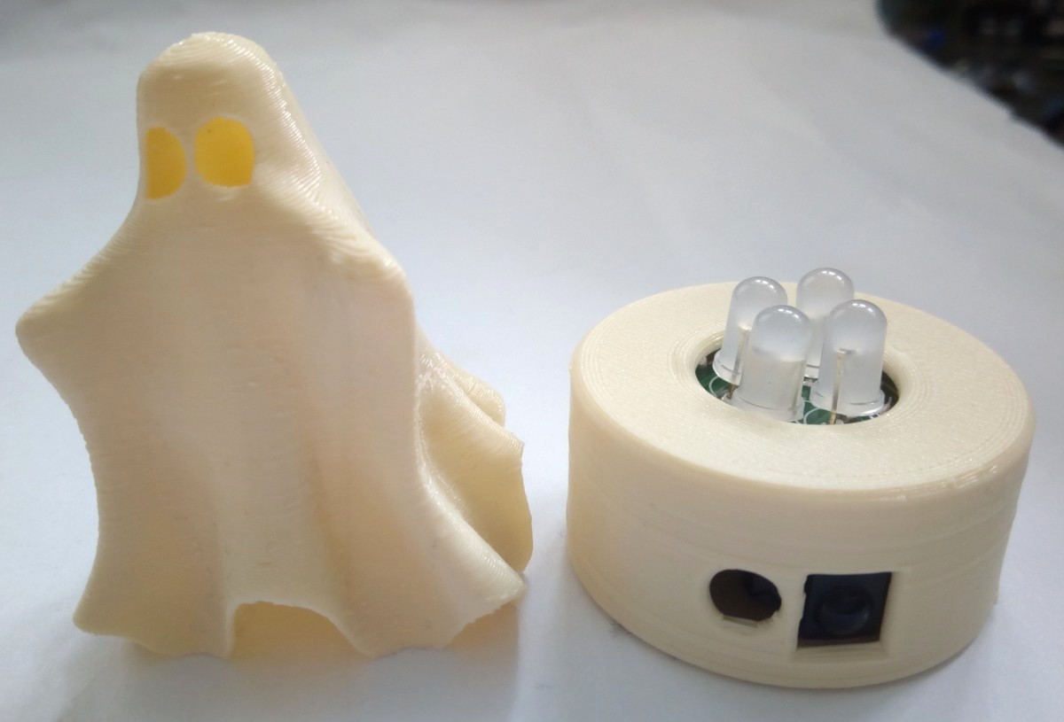
The simulation code is based on the great work of Mark Sherman. With most LED candles, the random flickering is rather silly and lacks the spooky element of candlelight: shadows cast by the candle move because the flame is in motion. With NeoCandle, four NeoPixels are arranged in a square, the intensity of the four LEDs forms a "center" of light balance that can be moved around smoothly.
This 'physics-based' candlelight has the following properties:
- The flame has a position and a velocity.
- If the position is not centered, the velocity will accelerate towards the center in proportion to the displacement (hooke's law of springs).
- The velocity has a very small damping value, which means that corrections towards the center always overshoot a bit (underdamped system).
- Random "pushes" into the center position of the light are performed to mimic random drafts.
- The strength of the drafts changes periodically (alternating periods of calm and windiness).
The control of NeoPixels with 8-bit microcontrollers is usually done with software bit-banging. However, this is particularly difficult at low clock rates due to the relatively high data rate of the protocol and the strict timing requirements. The essential protocol parameters for controlling the WS2812 NeoPixels (or similar 800kHz addressable LEDs) can be found in the datasheet.
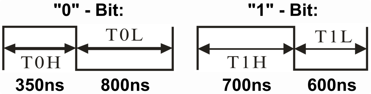
Fortunately, the timing is nowhere near as strict as the data sheet suggests. The following timing rules can be derived from the excellent articles by Josh Levine and Tim and should work with all 800kHz addressable LEDs:
| Pulse | Parameter | Min | Typical | Max |
|---|---|---|---|---|
| T0H | "0"-Bit, HIGH time | 65 ns | 350 ns | 500 ns |
| T1H | "1"-Bit, HIGH time | 625 ns | 700 ns | 8500 ns |
| T0L | "0"-Bit, LOW time | 450 ns | 800 ns | 8500 ns |
| T1L | "1"-Bit, LOW time | 450 ns | 600 ns | 8500 ns |
| TCT | Total Cycle Time | 1150 ns | 1250 ns | 9000 ns |
| RES | Latch, LOW time | 9 µs | 50 µs | 280 µs |
Apart from T0H, the maximum values can be even higher, depending on when the NeoPixels actually latch the sent data (with some types only after 280µs!). This also makes it possible to work without a buffer and thus without the use of SRAM. The software essentially only has to ensure that T0H is a maximum of 500ns and T1H is at least 625ns, so that the pixels can reliably differentiate "0" from "1" and that the time between sending two bytes is less than the latch time. Assuming that the microcontroller runs with a clock frequency of 8 MHz, the following simple bit-banging function for the transmission of a data byte to the NeoPixels string was implemented:
// Send a byte to the pixels string
void NEO_sendByte(uint8_t byte) {       // CLK  comment
  uint8_t count = 8;                    //      8 bits, MSB first
  asm volatile (
    "sbi  %[port], %[pin]   \n\t"       //  2   DATA HIGH
    "sbrs %[byte], 7        \n\t"       // 1-2  if "1"-bit skip next instruction
    "cbi  %[port], %[pin]   \n\t"       //  2   "0"-bit: DATA LOW after 3 cycles
    "add  %[byte], %[byte]  \n\t"       //  1   byte <<= 1
    "subi %[bit],  0x01     \n\t"       //  1   count--
    "cbi  %[port], %[pin]   \n\t"       //  2   "1"-bit: DATA LOW after 6 cycles
    "brne .-14              \n\t"       //  2   while(count)
    ::
    [port]  "I"   (_SFR_IO_ADDR(PORTB)),
    [pin]   "I"   (NEO_PIN),
    [byte]  "w"   (byte),
    [bit]   "w"   (count)
  );
}
When compiled, the function for bit-banging a data byte requires only 18 bytes of flash. The resulting timing values are shown in the following table:
| Pulse | Parameter | Clock Cycles | Time |
|---|---|---|---|
| T0H | "0"-Bit, HIGH time | 3 Cycles | 375 ns |
| T1H | "1"-Bit, HIGH time | 6 Cycles | 750 ns |
| T0L | "0"-Bit, LOW time | 8 Cycles | 1000 ns |
| T1L | "1"-Bit, LOW time | 4 Cycles | 500 ns |
| TCT | Total Cycle Time | 11/10 Cycles | 1375/1250 ns |
This results in a transfer rate of 762 kbps, at least for a single data byte. The implementation can certainly still be optimized in terms of speed, but this is already close to the maximum and more than sufficient for controlling only four NeoPixels. Remember that interrupts should be disabled during transmission, otherwise the timing requirements cannot be met.
There are three data bytes for each NeoPixel. These are transmitted in the order green, red and blue (this can be different for other types of NeoPixels) with the most significant bit first. The data for the NeoPixel, which is closest to the microcontroller, is output first, then for the next up to the outermost pixel. So this doesn't work like an ordinary shift register! After all color data have been sent, the data line must be kept LOW for at least 9 to 280 µs (depending on the type of NeoPixel) so that the transferred data is latched and the new colors are displayed.
The implementation of the candle simulation requires random numbers for a realistic flickering of the candle. However, the usual libraries for generating random numbers require a relatively large amount of memory. Fortunately, Łukasz Podkalicki has developed a lightweight random number generator based on Galois linear feedback shift register for the ATtiny13A, which is also used here, slightly adapted. When compiled, this function only requires 86 bytes of flash.
// Start state (any nonzero value will work)
uint16_t rn = 0xACE1;

// Pseudo random number generator
uint16_t prng(uint16_t maxvalue) {
  rn = (rn >> 0x01) ^ (-(rn & 0x01) & 0xB400);
  return(rn % maxvalue);
}The IR receiver implementation is based on TinyDecoder and requires 234 bytes of flash. Only the NEC protocol is supported, but this is used by almost all cheap IR remote controls. Alternatively, you can build such a remote control yourself with TinyRemote.
The IR NEC decoding function utilizes timer1 to measure the burst and pause lengths of the signal. The timer is automatically started and stopped or reset by the IR receiver via a pin change interrupt. The measured lengths are interpreted according to the NEC protocol and the transmitted code is calculated accordingly. The program was tested with the TSOP4838, but it should also work with other 38kHz IR receivers (note different pinout if necessary).
The output of the IR reciever is inverted (active LOW), a burst is indicated by a LOW signal, a pause by a HIGH signal. IR message starts with a 9ms leading burst followed by a 4.5ms pause. Afterwards 4 data bytes are transmitted, least significant bit first. A "0" bit is a 562.5µs burst followed by a 562.5µs pause, a "1" bit is a 562.5µs burst followed by a 1687.5µs pause. A final 562.5µs burst signifies the end of the transmission. According to the data sheet of the TSOP4838, the length of the output signal differs from the transmitted signal by up to 158µs, which the code must take into account. The four data bytes are in order:
- the 8-bit address for the receiving device,
- the 8-bit logical inverse of the address,
- the 8-bit key-dependend command and
- the 8-bit logical inverse of the command.
The Extended NEC protocol uses 16-bit addresses. Instead of sending an 8-bit address and its logically inverse, first the low byte and then the high byte of the address is transmitted. For a more detailed explanation on the NEC protocol refer to TinyRemote. Don't forget to define the used IR codes in the sketch!
// IR codes
#define IR_ADDR       0xEF00  // IR device address
#define IR_PWRON      0x03    // IR code for power on
#define IR_PWROFF 0x02 // IR code for power offOpen the NeoCandle Sketch and adjust the IR codes so that they match your remote control. Remember that only the NEC protocol is supported. If necessary, adjust the values for the LDR light sensor and the switch-off timer.
- Make sure you have installed ATtinyCore.
- Go to Tools -> Board -> ATtinyCore and select ATtiny25/45/85 (No bootloader).
- Go to Tools and choose the following board options:
- Chip: ATtiny25 or 45 or 85 (depending on your chip)
- Clock: 8 MHz (internal)
- Millis/Micros: disabled
- B.O.D.Level: disabled
- Leave the rest at the default settings
- Connect your programmer to your PC and to the ICSP header on the board.
- Go to Tools -> Programmer and select your ISP programmer (e.g. USBasp).
- Go to Tools -> Burn Bootloader to burn the fuses.
- Open NeoCandle sketch and click Upload.
- Make sure you have installed avrdude.
- Connect your programmer to your PC and to the ISCP header on the board.
- Open a terminal.
- Navigate to the folder with the hex-file.
- Execute the following command (if necessary replace "t85" with your chip and "usbasp" with the programmer you use):
avrdude -c usbasp -p t85 -U lfuse:w:0xe2:m -U hfuse:w:0xd7:m -U efuse:w:0xff:m -U flash:w:neocandle.hex
- Make sure you have installed avr-gcc toolchain and avrdude.
- Connect your programmer to your PC and to the ICSP header on the board.
- Open a terminal.
- Navigate to the folder with the makefile and the Arduino sketch.
- Run
DEVICE=attiny85 PROGRMR=usbasp make installto compile, burn the fuses and upload the firmware (change DEVICE and PROGRMR accordingly).
- Connect a 5V power supply to the Micro-USB socket or a battery to the respective board header.
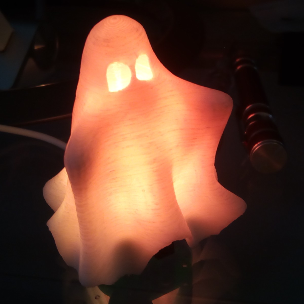
- The NeoCandle should immediately mimic the flickering of a candle. The device is now in TIMER mode and switches off automatically after the time programmed in the code has elapsed. You can switch it off at any time by pressing the power-off button on the IR remote control and switch it back on with the power-on button.
- If the power-on button on the IR remote control is pressed while the NeoCandle is switched on, it changes to LDR mode. This change is indicated by a short blue light animation. In LDR mode, NeoCandle switches on and off automatically depending on the intensity of the ambient light. Pressing the power-on or power-off button on the IR remote control switches back to TIMER mode.
- ATtiny25/45/85 Datasheet
- WS2812 Datasheet
- TSOP4838 Datasheet
- GL5528 Datasheet
- Josh Levine's Article about NeoPixels
- Tim's Article about NeoPixels
- AdaFruit NeoPixel Überguide
- Candle Simulation Implementation by Mark Sherman
- Lightweight Random Number Generator by Łukasz Podkalicki
- IR Receiver Implementation
- TinyCandle for ATtiny13A

This work is licensed under Creative Commons Attribution-ShareAlike 3.0 Unported License. (http://creativecommons.org/licenses/by-sa/3.0/)