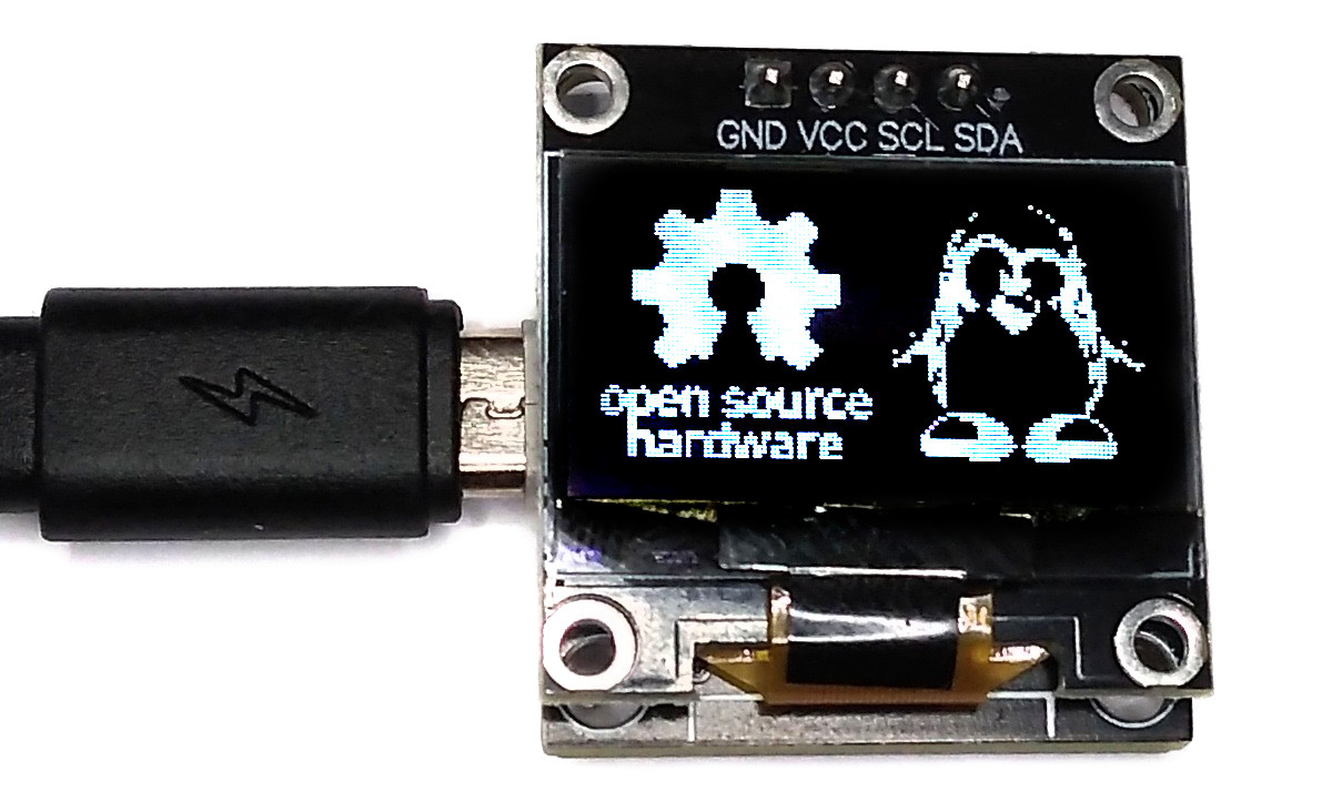
USB-OLED is a simple USB-controlled 128x64 pixels I²C OLED display. The CH552E (or CH554E) microcontroller builds a USB Communication Device Class (CDC) for serial communication over USB, which can be used to transfer data from the PC to the OLED. An integrated buzzer offers the possibility of outputting acoustic signals.
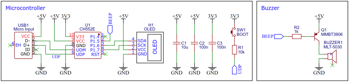
The CH552E is a low-cost, enhanced E8051 core microcontroller compatible with the MCS51 instruction set. It has an integrated USB 2.0 controller with full-speed data transfer (12 Mbit/s) and supports up to 64 byte data packets with integrated FIFO and direct memory access (DMA). The CH552E has a factory built-in bootloader so firmware can be uploaded directly via USB without the need for an additional programming device.
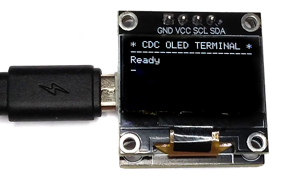
This firmware implements a simple terminal for displaying text messages on the OLED. It can be use with any serial monitor on your PC. The integrated buzzer gives an acoustic signal for every message received.
Operating Instructions:
- Connect the board via USB to your PC. It should be detected as a CDC device.
- Open a serial monitor and select the correct serial port (BAUD rate doesn't matter).
- Send a text message, it should be displayed on the OLED.
On Linux you can also send text messages via a terminal:
echo "Hello World!\n" > /dev/ttyACM0
This firmware is designed to function as a simple USB to I²C bridge, which enables communication between a PC and an I²C-enabled device, such as an OLED screen. In order for data transmission to begin, the PC software must first set the RTS (Ready To Send) flag. This action triggers the firmware on the microcontroller to initiate the start condition on the I²C bus, signaling that data will be transferred.
Once the start condition has been set, all data bytes that are sent via USB CDC are passed directly to the I²C bus. It is important to note that each data stream must begin with the I²C write address of the I²C slave device, in this case, the OLED screen.
When all data bytes have been transferred, the PC software must clear the RTS flag again, signaling the end of the data transmission. This causes the microcontroller to set the stop condition on the I²C bus, effectively ending the communication. This mode of operation allows for full control of the OLED via the PC, and in principle, the firmware could also be used to control other I²C devices.
Two attached Python scripts show the PC-side implementation of the I²C bridge as an example. "bridge-demo.py" shows and scrolls an image, "bridge-conway.py" plays Conway's Game of Life on the OLED.
Operating Instructions:
- Connect the board via USB to your PC. It should be detected as a CDC device.
- Run
python3 bridge-demo.pyorpython3 bridge-conway.py.
This firmware does the same as the CDC bridge, but here the device is identified as a USB Human Interface Device (HID). The advantage is that no driver installation is necessary under Windows either. However, the device can then only be controlled via the appropriate software on the PC side (in this case the attached Python scripts). In addition, administrator rights may be required for the software to detach the device interface from the kernel. The data rate is significantly slower with HID (interrupt transfer) than with CDC (bulk transfer), which is negligible in this application, since the bottleneck is the I²C bus.
Data is sent to the device via HID reports with a maximum packet size of 64 bytes. For each packet received, the device first sets the start condition on the I²C bus, then transfers the data over the I²C bus and then sets the stop condition. Each packet must therefore start with the I²C write address of the slave device.
On Linux you can grant access permission to the HID device by executing the following commands:
echo 'SUBSYSTEM=="usb", ATTR{idVendor}=="16c0", ATTR{idProduct}=="05df", MODE="666"' | sudo tee /etc/udev/rules.d/99-HID_data.rules
sudo service udev restart
Operating Instructions:
- Connect the board via USB to your PC. It should be detected as a HID device.
- Run
python3 hid-bridge-demo.pyorpython3 hid-bridge-conway.py.
This firmware implements a simple USB vendor class to I²C bridge. The start and stop condition on the I²C bus is set according to an appropriate vendor class control request. Data of any length is sent to the device at high speed via bulk transfer, which is passed directly to the slave device via I²C. Each data stream must start with the I²C write address of the slave device.
Vendor control requests can also be used to control the buzzer or put the microcontroller into boot mode.
This firmware also includes an experimental implementation of a Windows Compatible ID (WCID). This allows to use the device without manual driver installation on Windows systems. However, since I (un)fortunately do not have a Windows system, this function is untested. More information about WCID can be found here. The WCID feature can be switched on or off in the configuration file (config.h). If not used, a manual installation of the libusb-win32 driver via the Zadig tool is required on Windows systems.
Operating Instructions:
- Connect the board via USB to your PC. It should be detected as a vendor class device.
- Run
python3 vendor-bridge-demo.pyorpython3 vendor-bridge-conway.py.
On Linux you do not need to install a driver. However, by default Linux will not expose enough permission to upload your code with the USB bootloader. In order to fix this, open a terminal and run the following commands:
echo 'SUBSYSTEM=="usb", ATTR{idVendor}=="4348", ATTR{idProduct}=="55e0", MODE="666"' | sudo tee /etc/udev/rules.d/99-ch55x.rules
sudo service udev restart
For Windows, you need the CH372 driver. Alternatively, you can also use the Zadig Tool to install the correct driver. Here, click "Options" and "List All Devices" to select the USB module, and then install the libusb-win32 driver. To do this, the board must be connected and the CH55x must be in bootloader mode.
A brand new chip starts automatically in bootloader mode as soon as it is connected to the PC via USB. Once firmware has been uploaded, the bootloader must be started manually for new uploads. To do this, the board must first be disconnected from the USB port and all voltage sources. Now press the BOOT button and keep it pressed while reconnecting the board to the USB port of your PC. The chip now starts again in bootloader mode, the BOOT button can be released and new firmware can be uploaded within the next couple of seconds.
Install the SDCC Compiler. In order for the programming tool to work, Python3 must be installed on your system. To do this, follow these instructions. In addition pyusb must be installed. On Linux (Debian-based), all of this can be done with the following commands:
sudo apt install build-essential sdcc python3 python3-pip
sudo pip install pyusb
- Open a terminal.
- Navigate to the folder with the makefile.
- Connect the board and make sure the CH55x is in bootloader mode.
- Run
make flashto compile and upload the firmware. - If you don't want to compile the firmware yourself, you can also upload the precompiled binary. To do this, just run
python3 ./tools/chprog.py firmware.bin.
Install the Arduino IDE if you haven't already. Install the CH55xduino package by following the instructions on the website.
- Copy the .ino and .c files as well as the /src folder together into one folder and name it like the .ino file.
- Open the .ino file in the Arduino IDE.
- Go to Tools -> Board -> CH55x Boards and select CH552 Board.
- Go to Tools and choose the following board options:
- Clock Source: 16 MHz (internal)
- Upload Method: USB
- USB Settings: USER CODE /w 266B USB RAM
- Connect the board and make sure the CH55x is in bootloader mode.
- Click Upload.
On Linux you do not need to install a CDC driver. On Windows you will need the Zadig tool to install the correct driver for the CDC device. Click "Options" and "List All Devices" to select the CDC device, then install the CDC driver.
For some Python scripts to work, PySerial must be installed. This can be done with the following command:
pip install pyserial
- EasyEDA Design Files
- CH551/552 Datasheet
- SSD1306 Datasheet
- SDCC Compiler
- CH55x SDK for SDCC
- ATtiny85 TinyTerminal
- 128x64 OLED on Aliexpress

This work is licensed under Creative Commons Attribution-ShareAlike 3.0 Unported License. (http://creativecommons.org/licenses/by-sa/3.0/)