Current Build Guide
This is the current build guide for Pepper which should be used for all full DIY kits purchased after April 2022. This covers both DIY kits bought from Thonk and from shop.bela.io. Your PCB will be marked with rev2.
If you bought your own components please make sure you have bought the most up to date BOM. If you purchased your components before March 2022 then please follow this legacy build guide for rev2.
This is not an overly complicated build but it might be a bit tricky for first-time solderers. If that's you then please check out this soldering guide and do a few practice circuits before taking on this build. For an experienced diyer this module should take an afternoon to solder up and configure and then you'll be making sound!
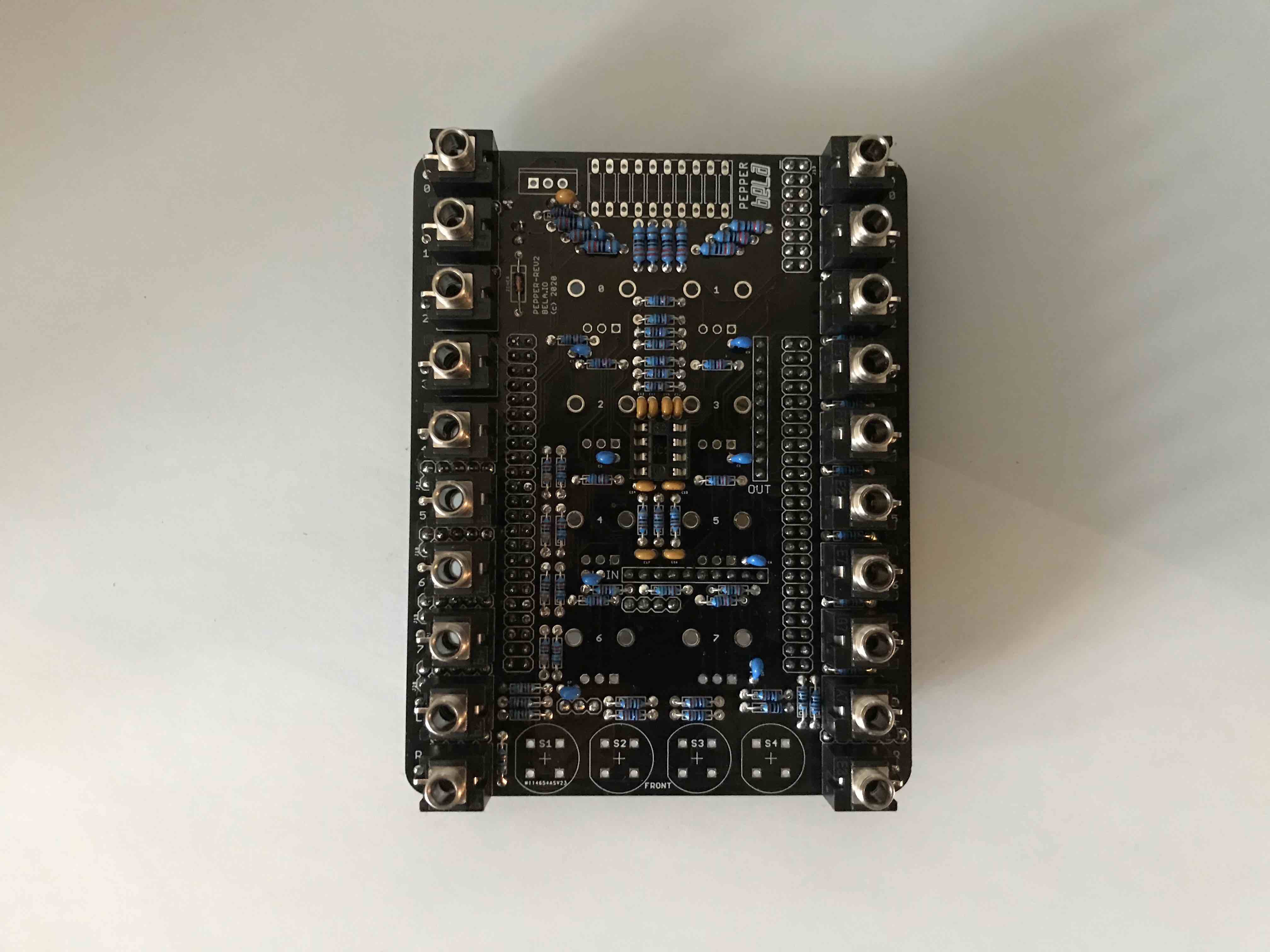
- add resistors R26-R35 (220) for the LED Bargraph

- add resistors R1, R3, R5, R12, R17, R19, R21, R23 (150K) and R2, R4, R6, R9 (68K) for the voltage dividers. NOTE: this image shows old resistor values and shall be updated soon. Make sure and put the correct value in the correct place.
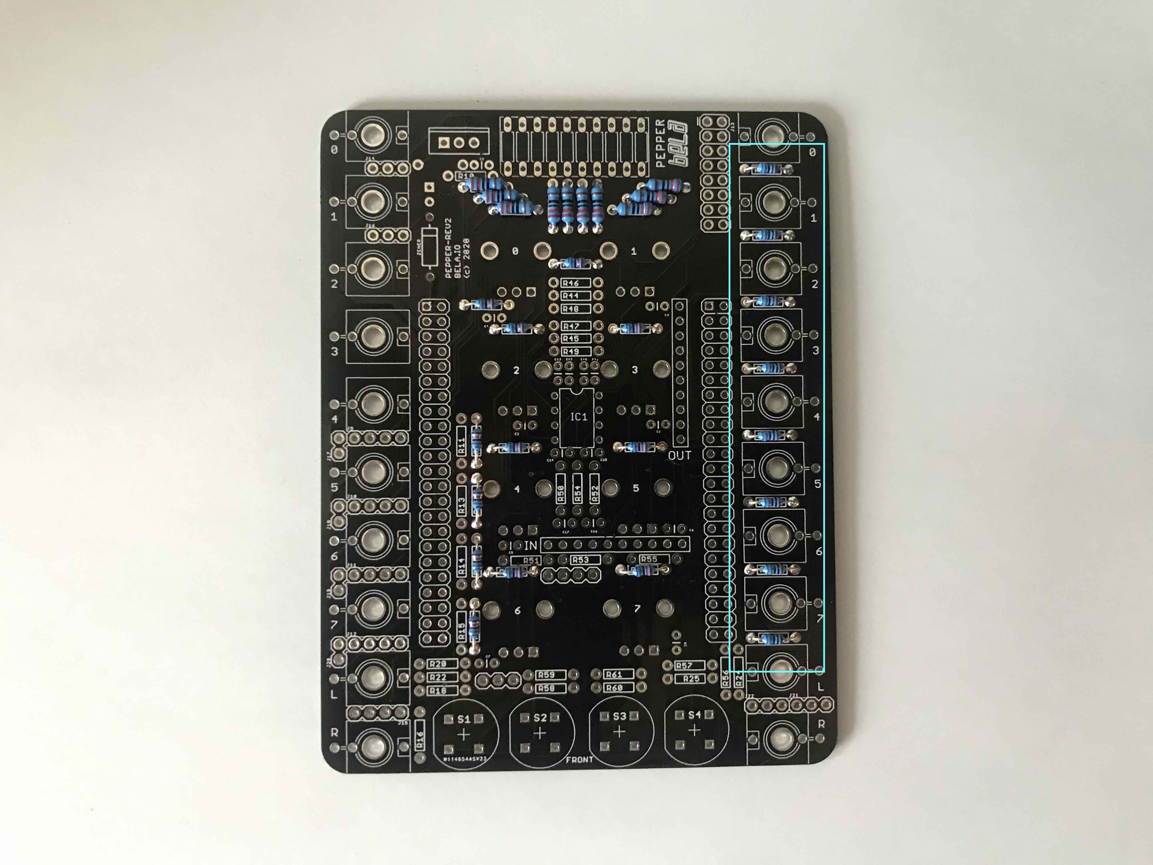
- add resistors R36 - R43 (680) for the analog outputs.
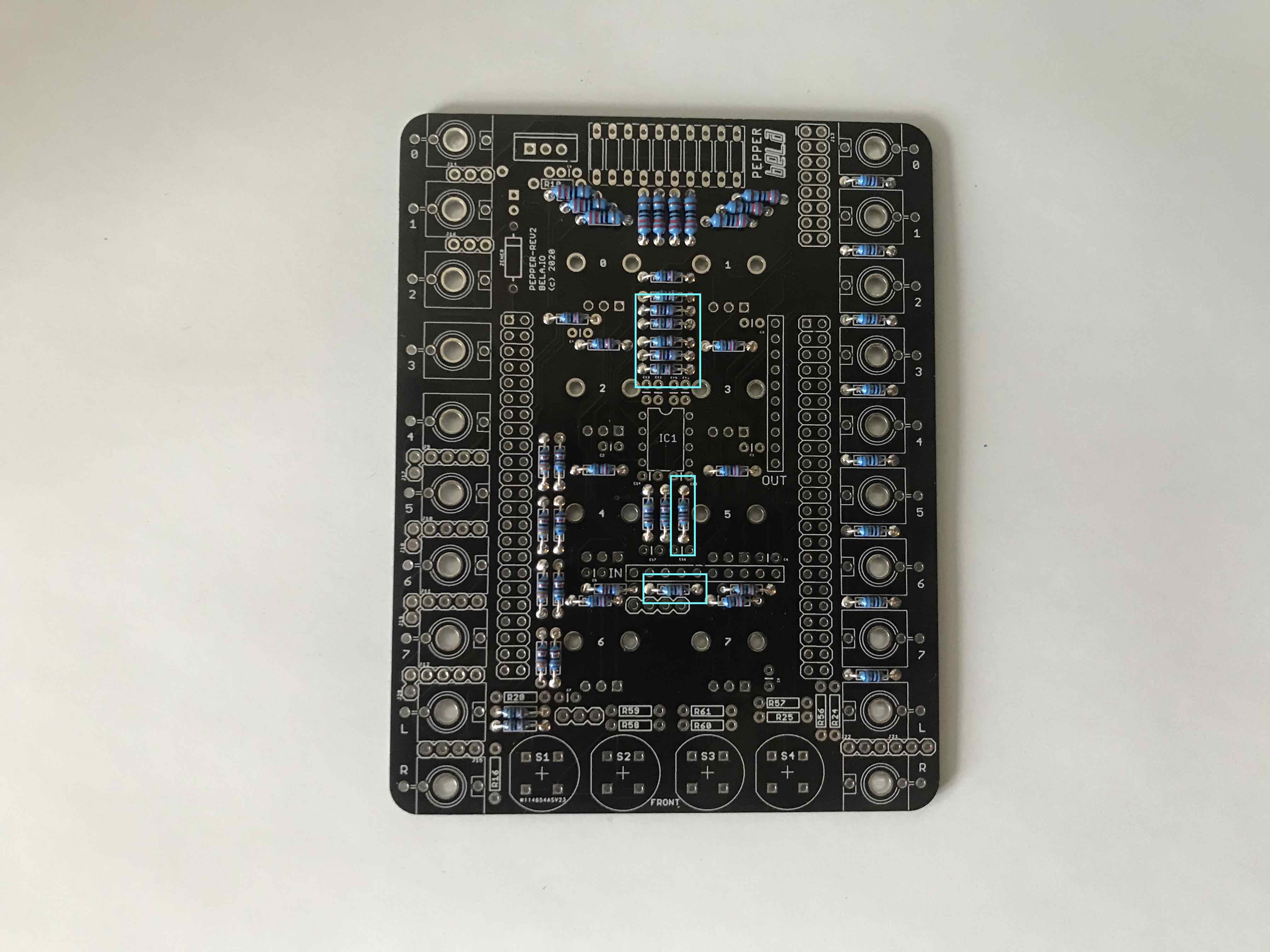
- add resistors R48, R49, R54, R55, R22, R18 (15K) for the audio inputs and outputs.
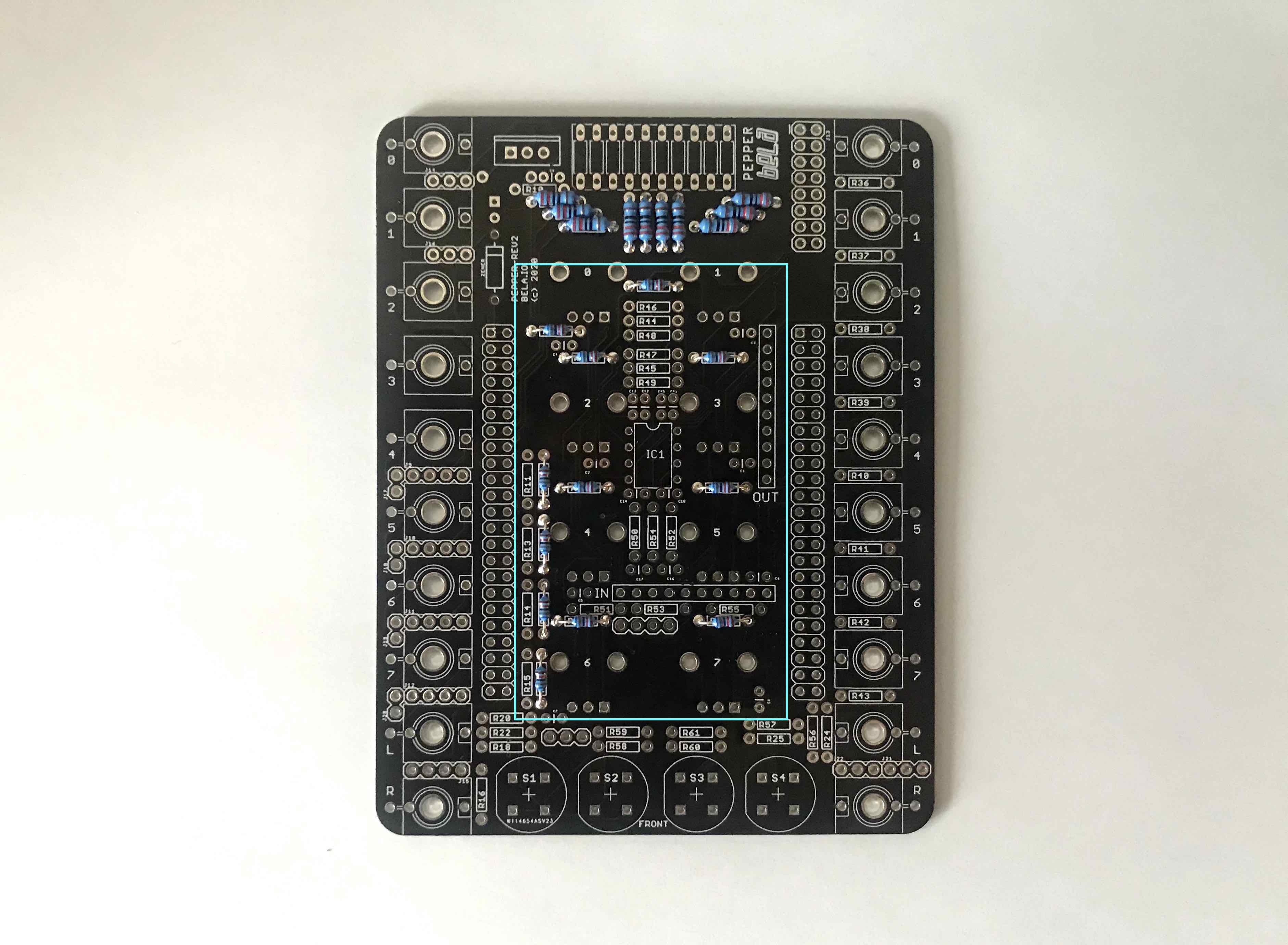
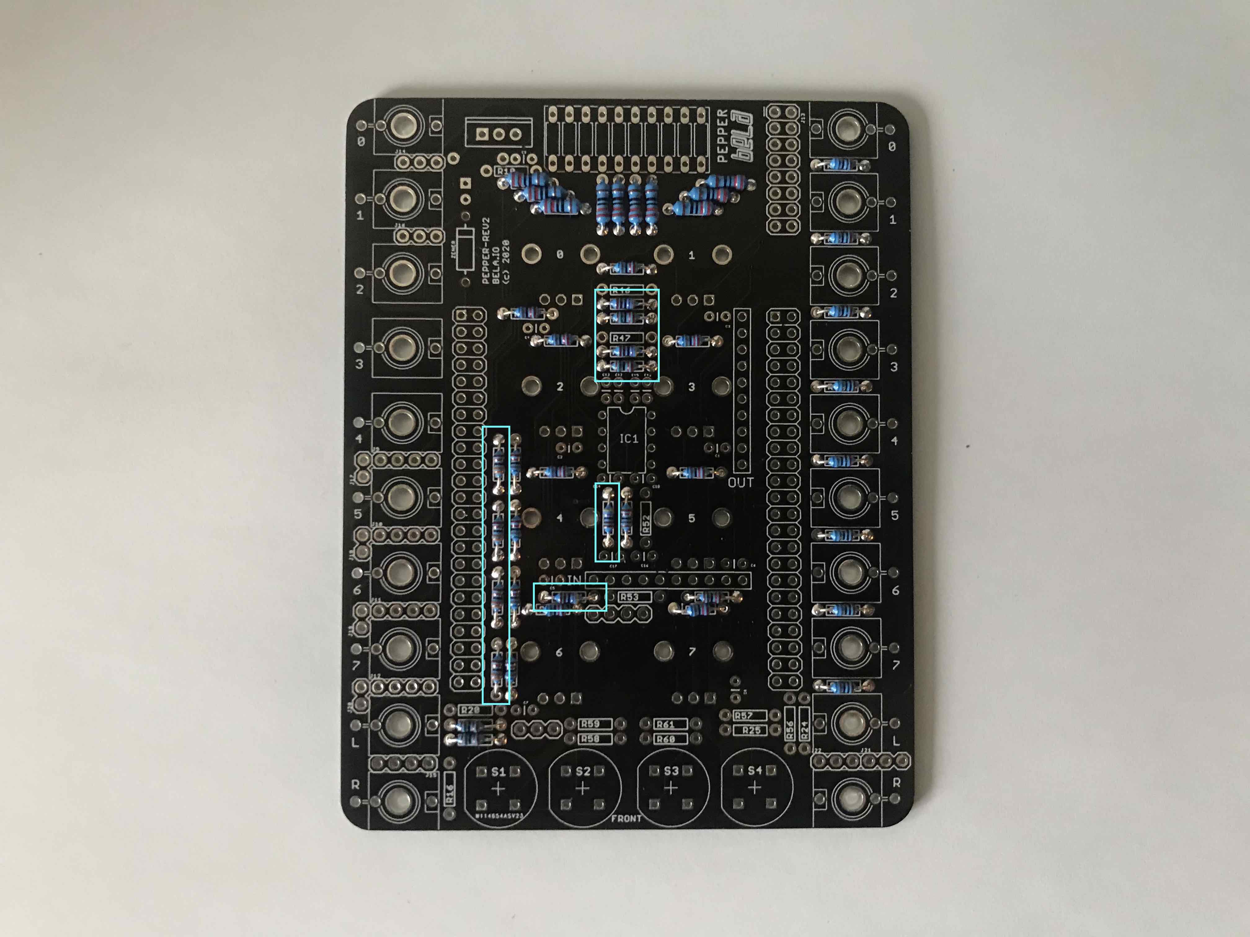
- add resistors R44, R45, R50, R51 (4K7) for the audio amplifier and R11, R13, R14, R15 (33K) for the digital part of the voltage dividers.
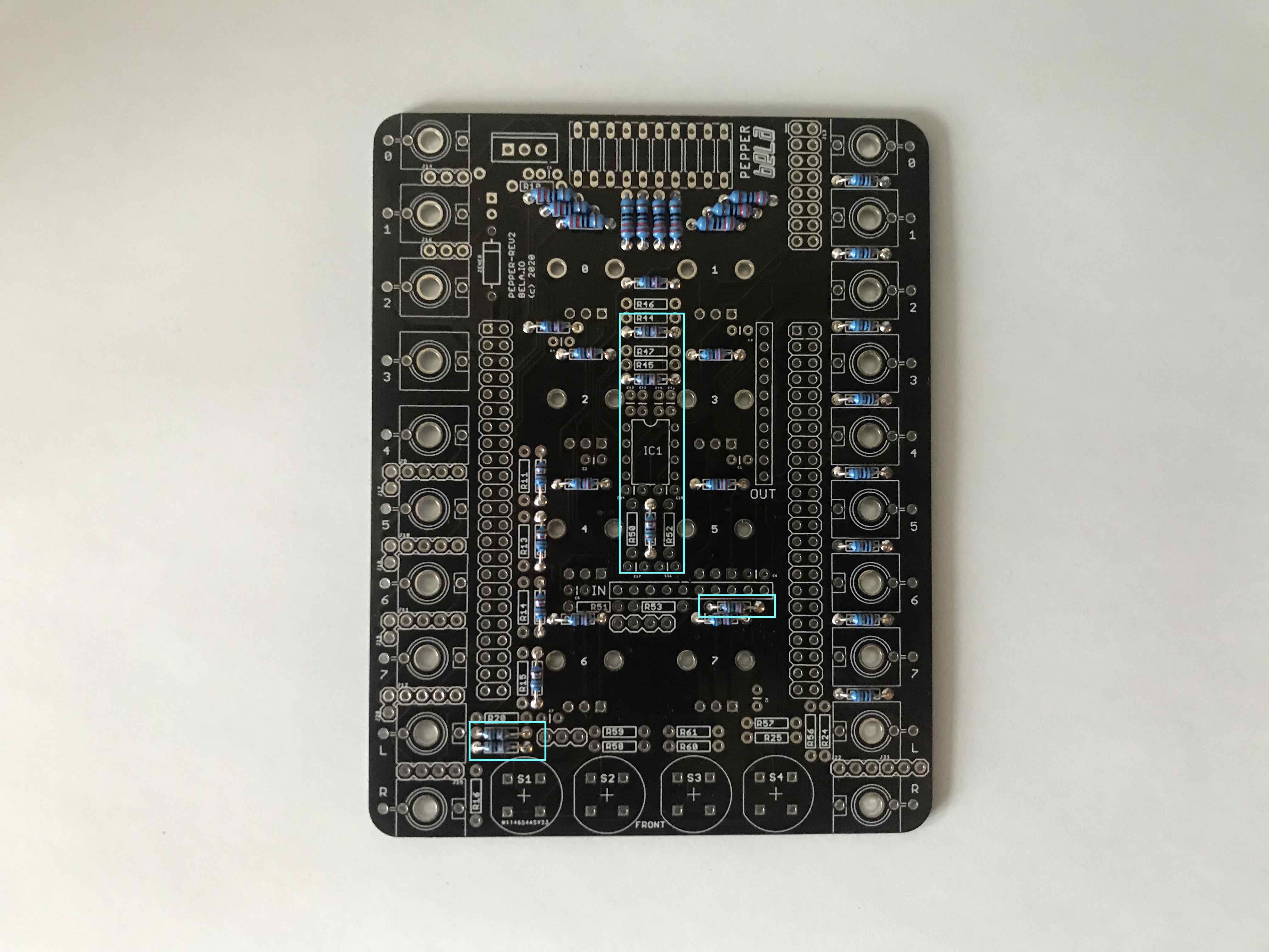
- add resistors R46, R47, R52, R53 (5K6) for the audio amplifier
- add resistors R58, R59, R60, R61 (100K) for the buttons
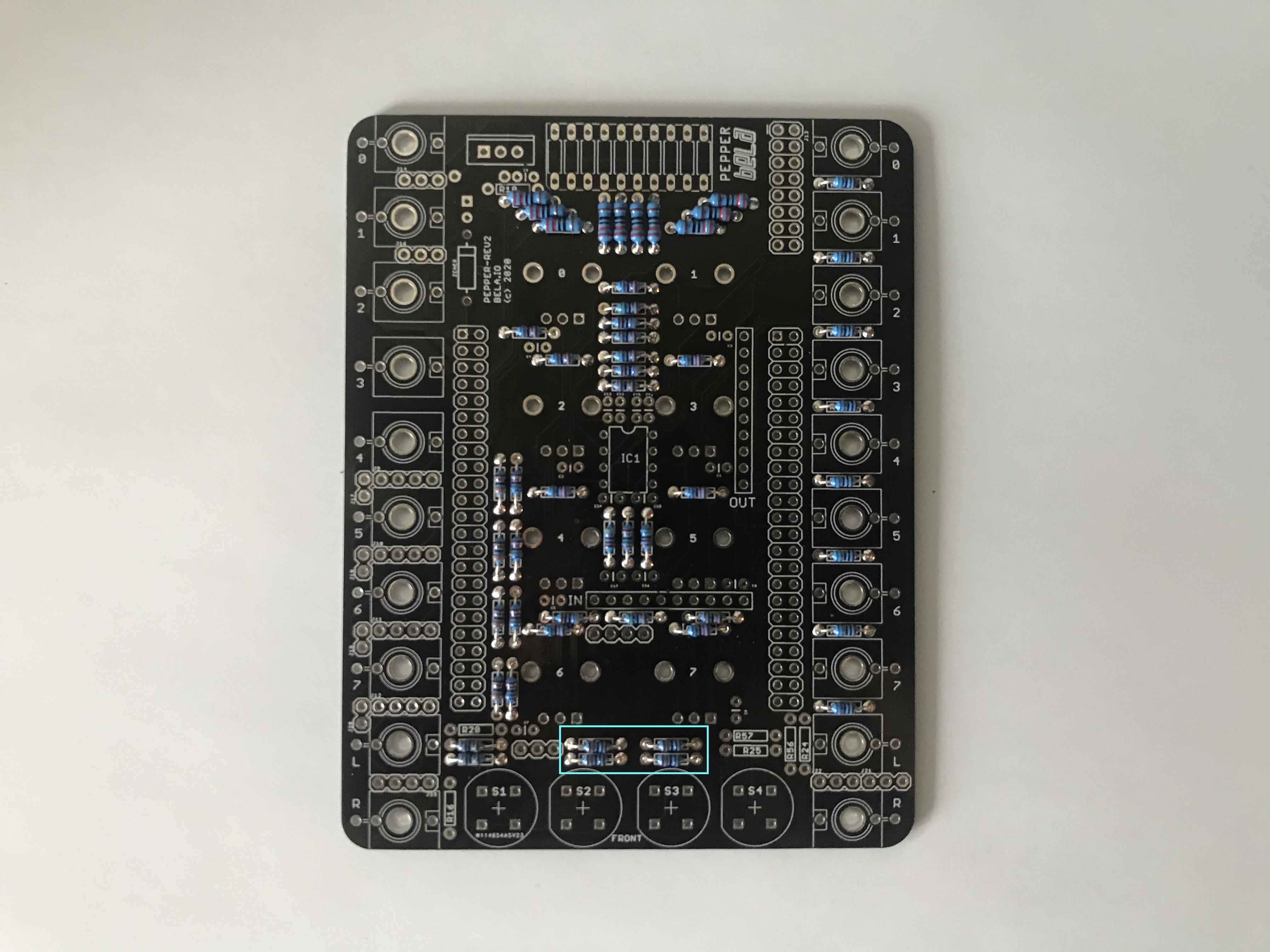
- add the remaining resistors:
- for audio input R16, R20 (82K)
- for audio output R25, R56 (100R)
- for audio output R24, R57 (1K) and R10 (1K) for the regulator

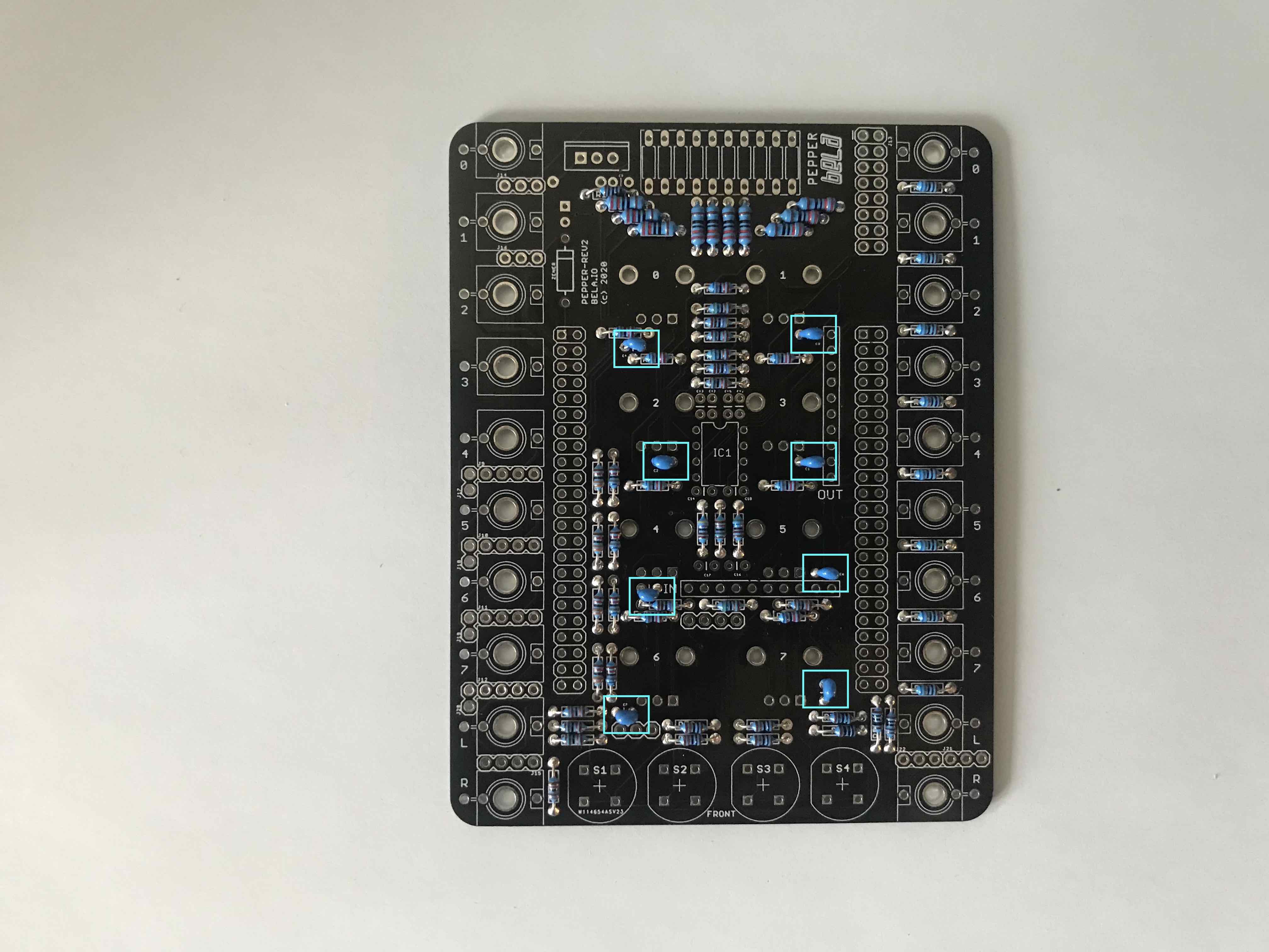
- add the 220pF (221) capacitors C1 - C8 for the pots.
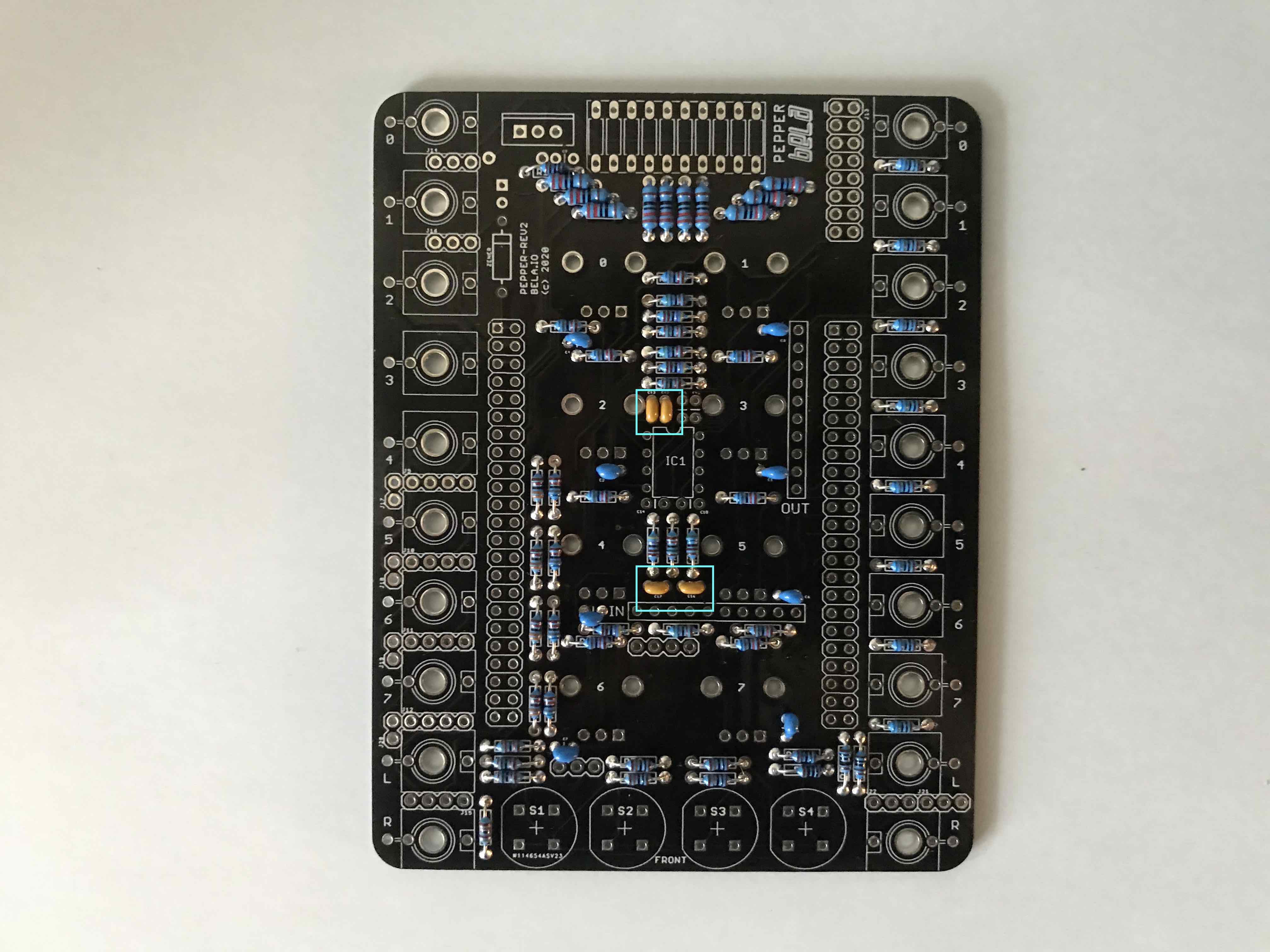
- add the 1nF (102) capacitors C12, C13, C16, C17.
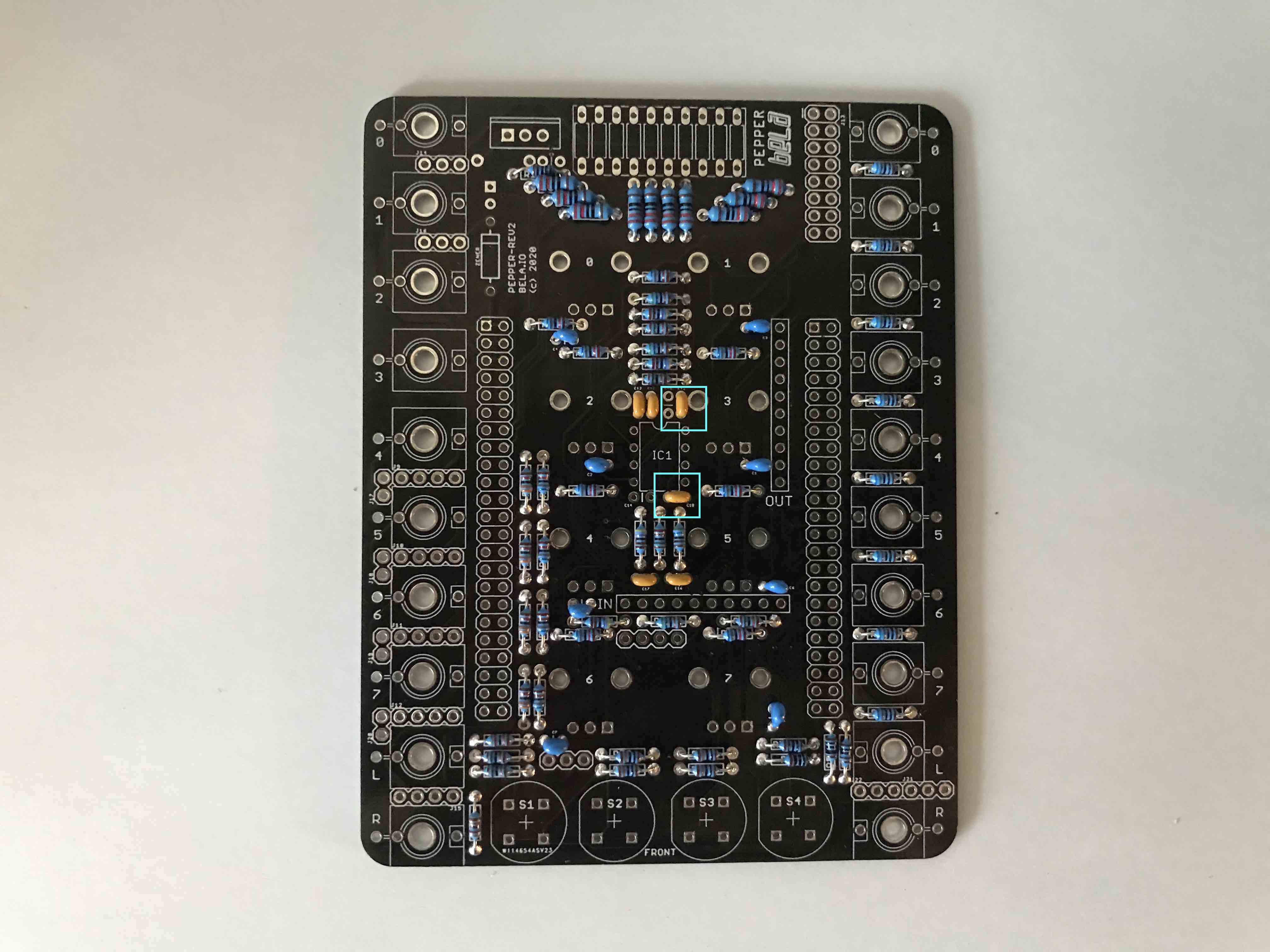
- add the 0.1nF (100 or 101 depending on manufacturer) capacitors C11, C18.
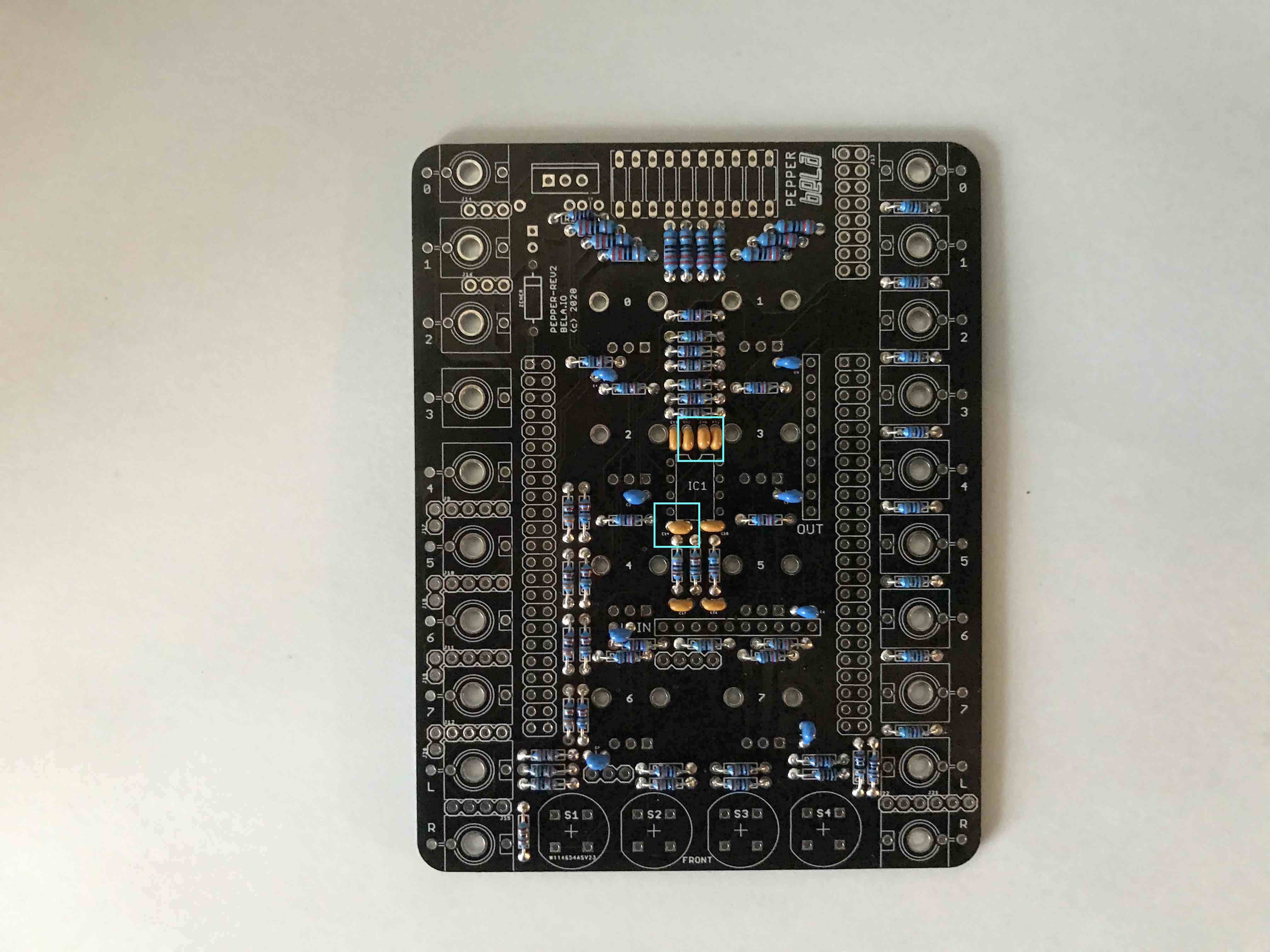
- add the 0.1uF (104) capacitors C14, C15.
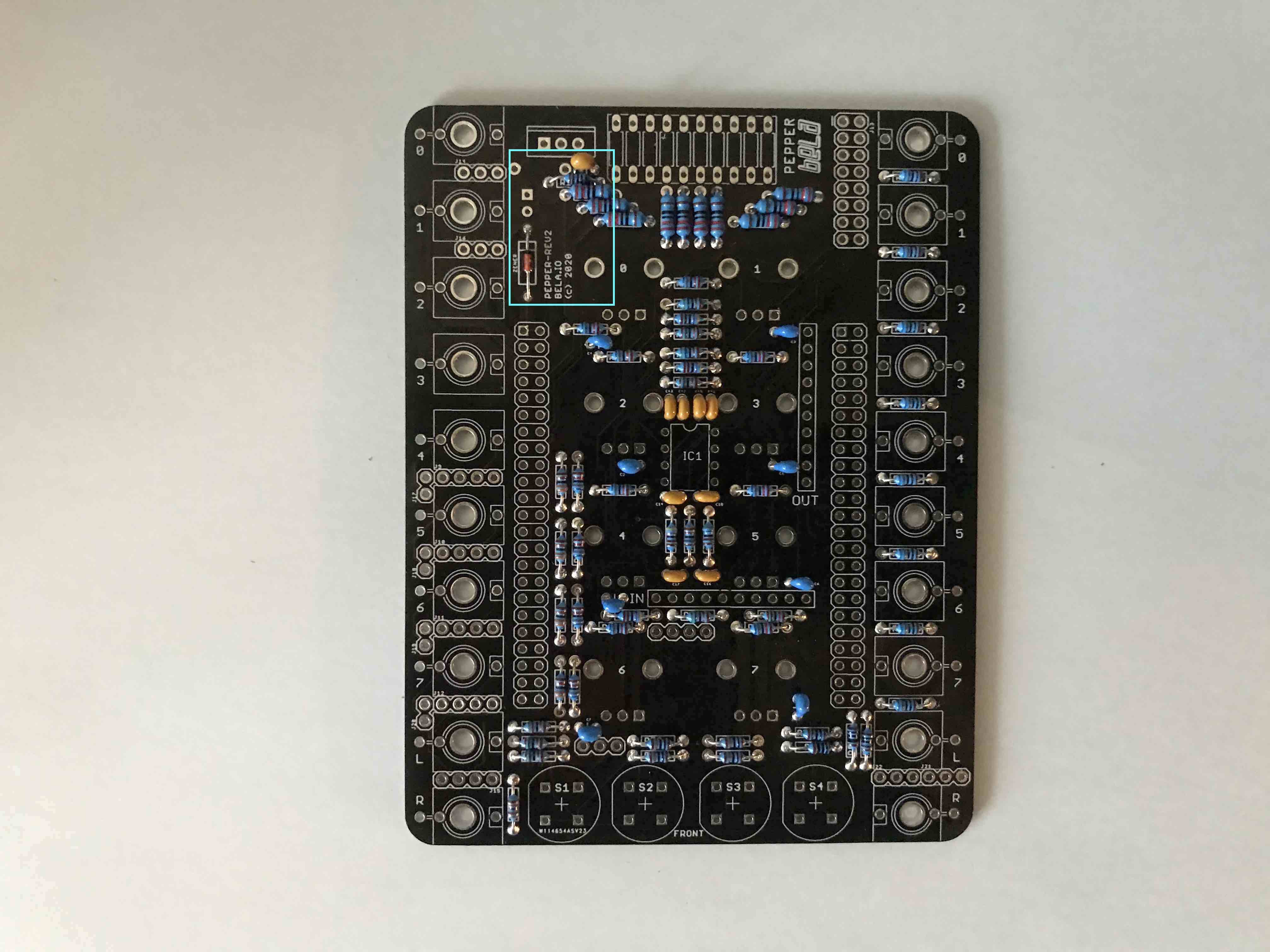
- add the final capacitor C9 (0.1uF 104) and the zener diode (make sure to get the polarity of the diode correct, match the line on the diode to the line on the silkscreen).
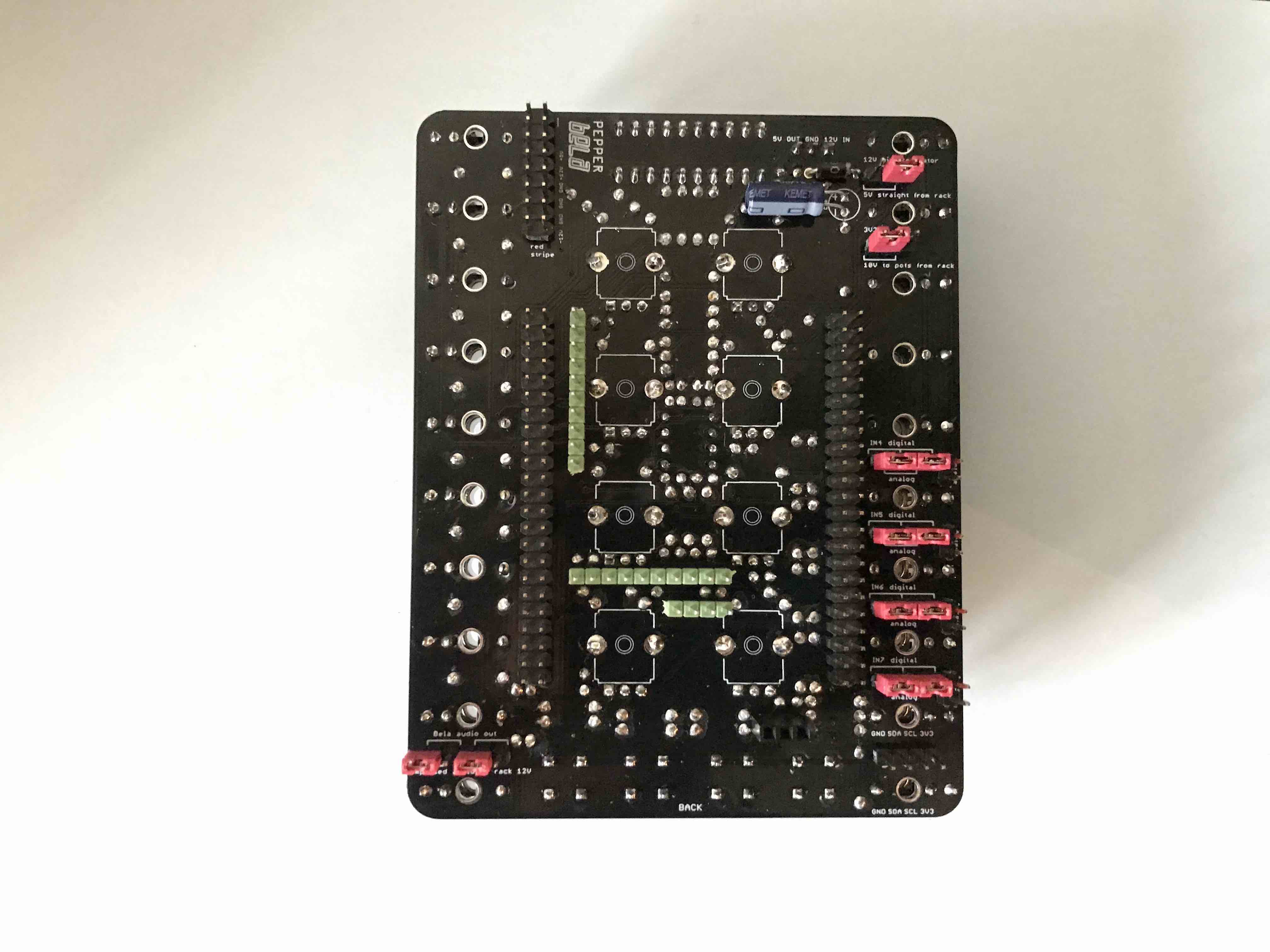
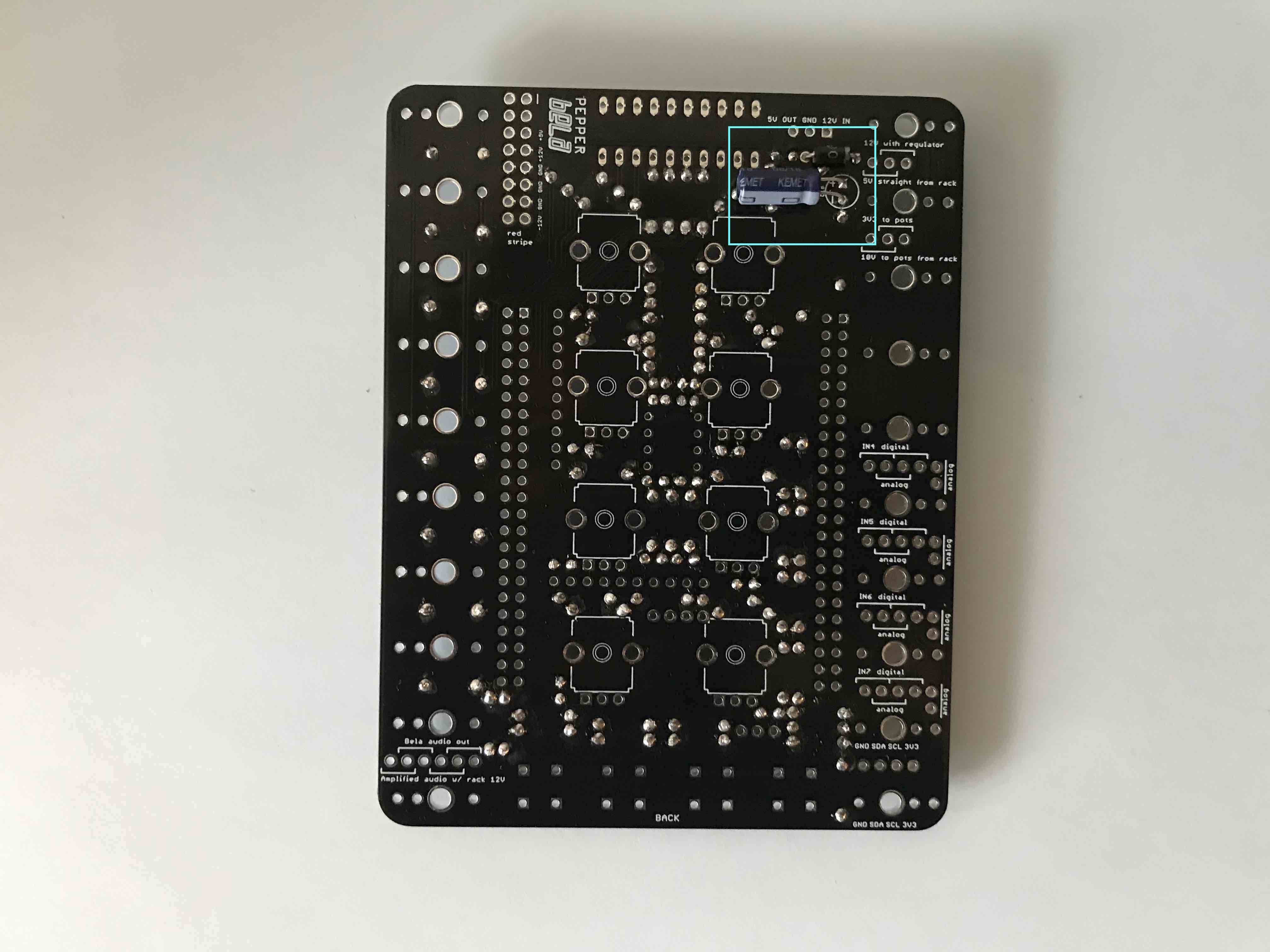
- attach the flyback diode (1N4148, 1N4500, IN5400 or equivalent) and electrolytic capacitor to the back of the PCB. Again make sure you get the polarity of both components correct!
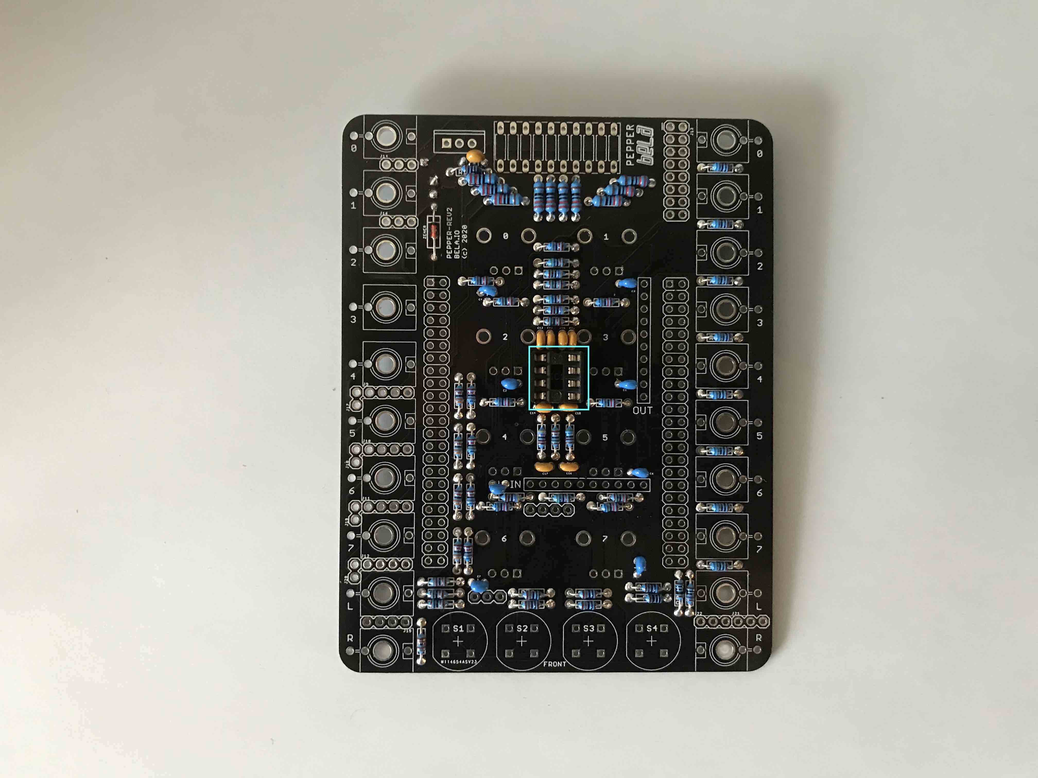
- add the cradle for the IC in the middle of the PCB.
- attach the first batch of male headers to the board as shown in the image below. It's important that these are attached at a right angle to the board otherwise you'll have problems getting the Bela board to fit on top.
- Tip 1 - use a breadboard to hold the pins upright and place the board on top to solder
- Tip 2 – for single row headers, solder a single pin, and then use your fingers to position the header correctly while heating the soldered pin with the iron.
NOTE: depending on your rails it might be a tight fit if you solder in the full 16 pin power connection. If you know you will run the module off of 12V then you can just solder pins to the bottom 10 pins of the power connection to make fitting into your rack easier.
NOTE: if you bought the full DIY kit from us then we recommend checking the Eurorack Power Cable which is included. This will be 10 pin on the side which attaches to the module, and 16 pins on the side which attached to the power bus. For that reason you should solder only the bottom ten pins.
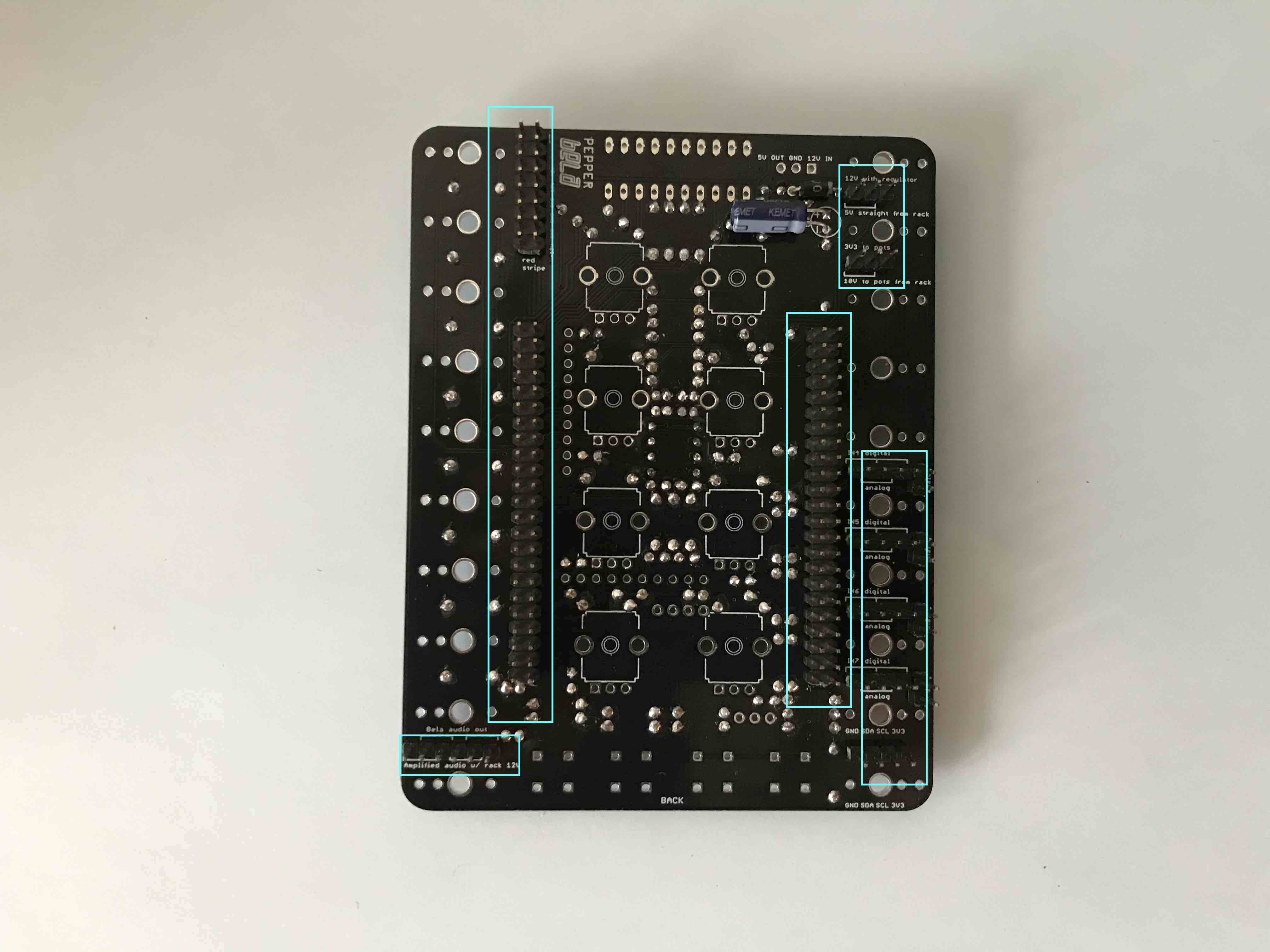
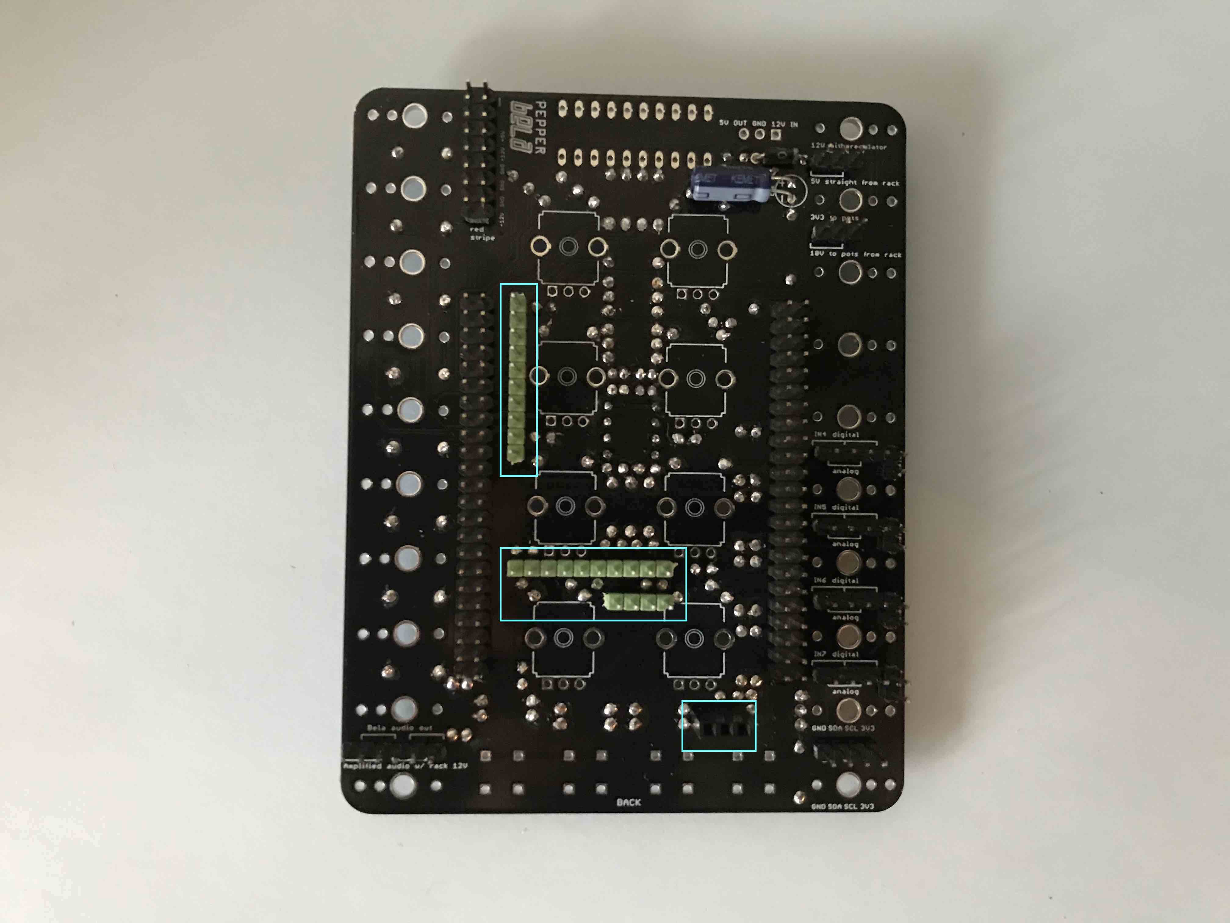
- attach the second group of longer headers to the board as well as the 3 pin female socket towards the bottom.
NOTE: it is recommended that you use the slightly longer pin headers (8mm) on the two rows of 10 that make contact with the analog input and output of Bela and the row of three pins that connects to the line out of Bela. If you don't have longer headers then normal sized pin headers (6mm) will suffice but you need to make sure that the cape and PCB and pushed together very tightly.
- attach the 3.5m sockets. Before soldering place the faceplate over the sockets to ensure correct alignment and height once the module is complete and the faceplate has been added.
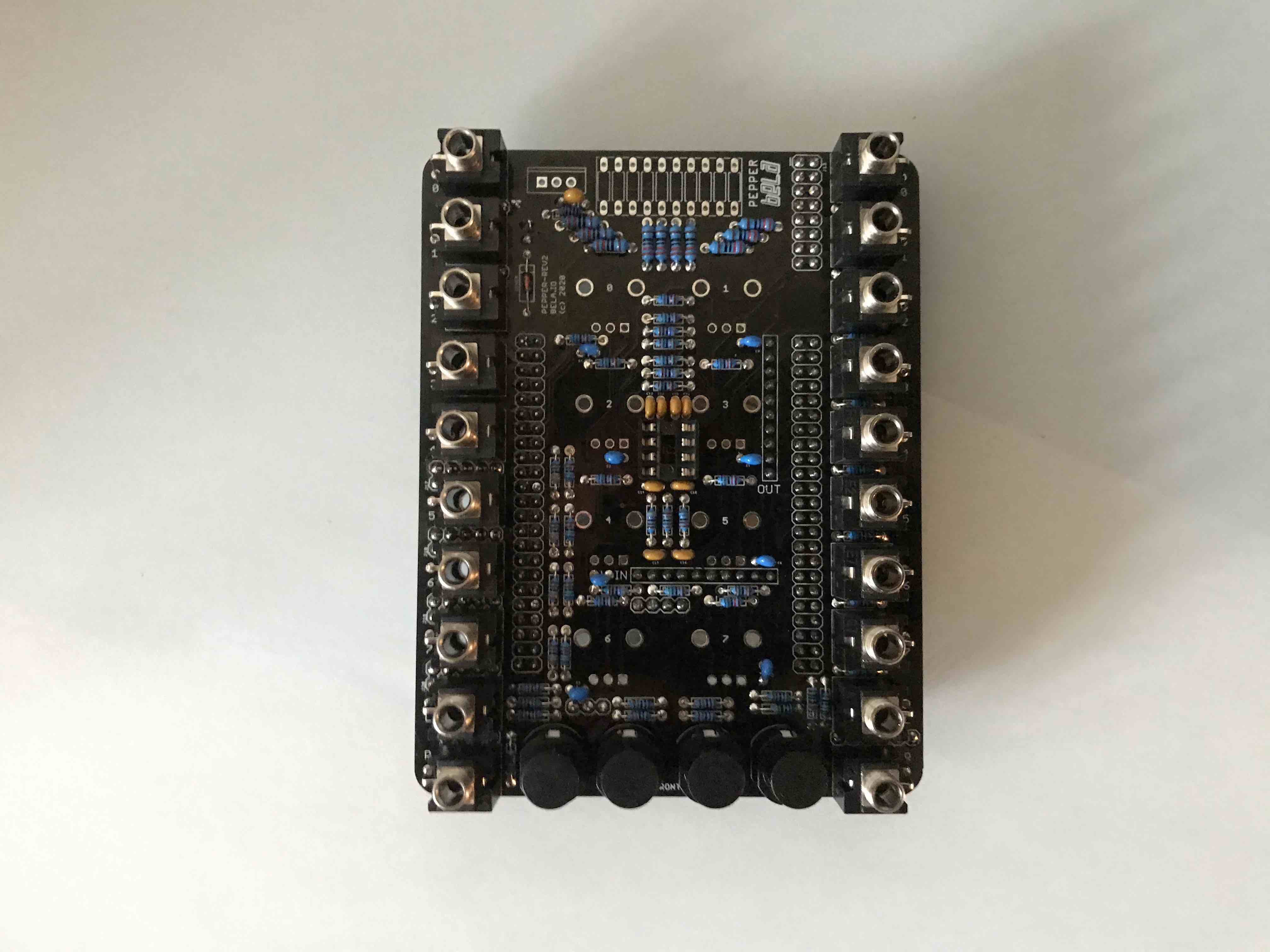
- attach the four buttons. Make sure these fit flush to the PCB to avoid any alignment issues when fitting the faceplate. The flat edge of the plastic casting should face to the left when you look at it as shown in the picture below.
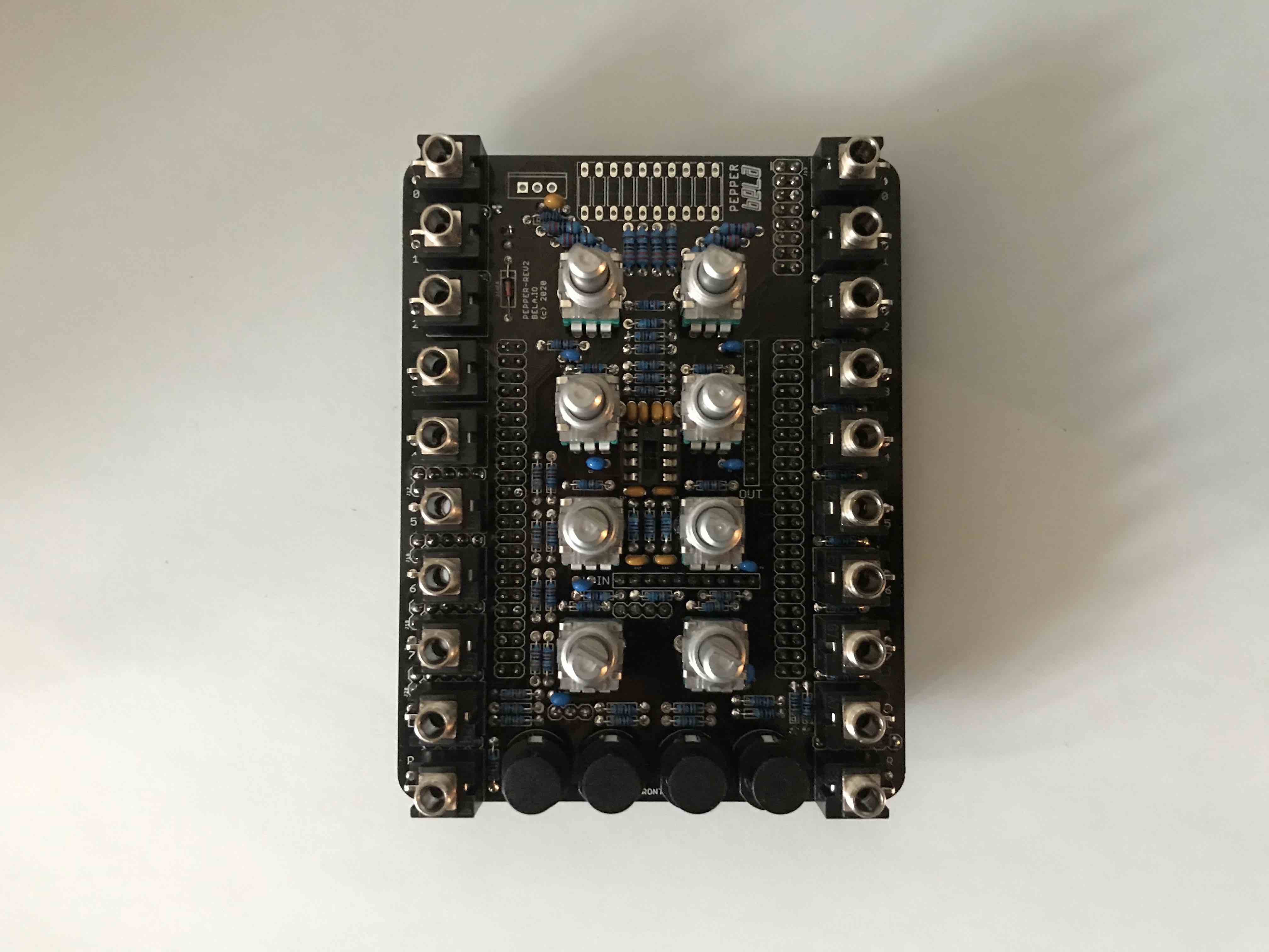
- attach the 8 100K potentiometers. Before soldering in the side supports check alignment with the faceplate. Cut lugs on the top of the pot if necessary.
- add the regulator. The text of the regulator should face towards the bottom of the PCB.
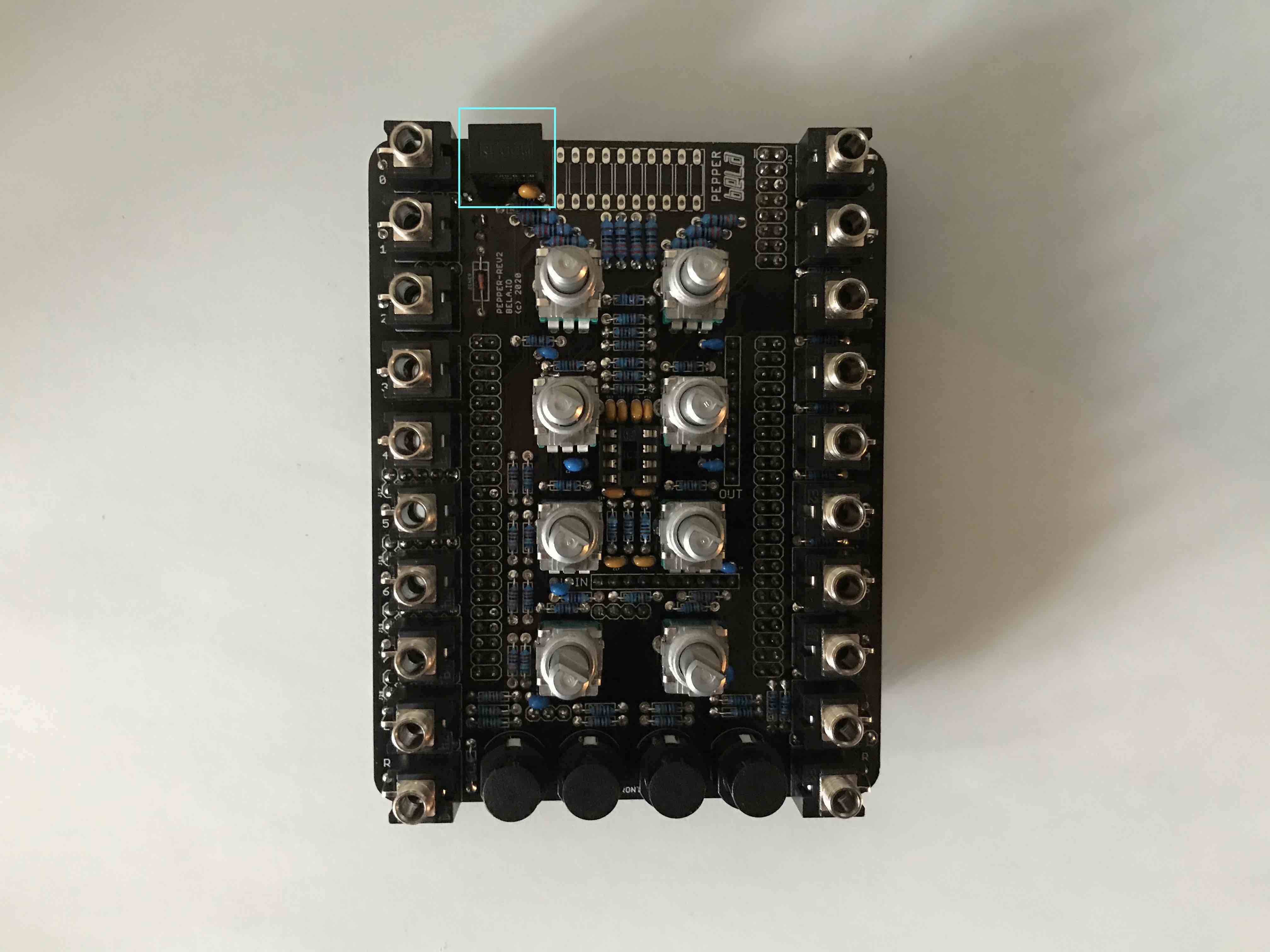
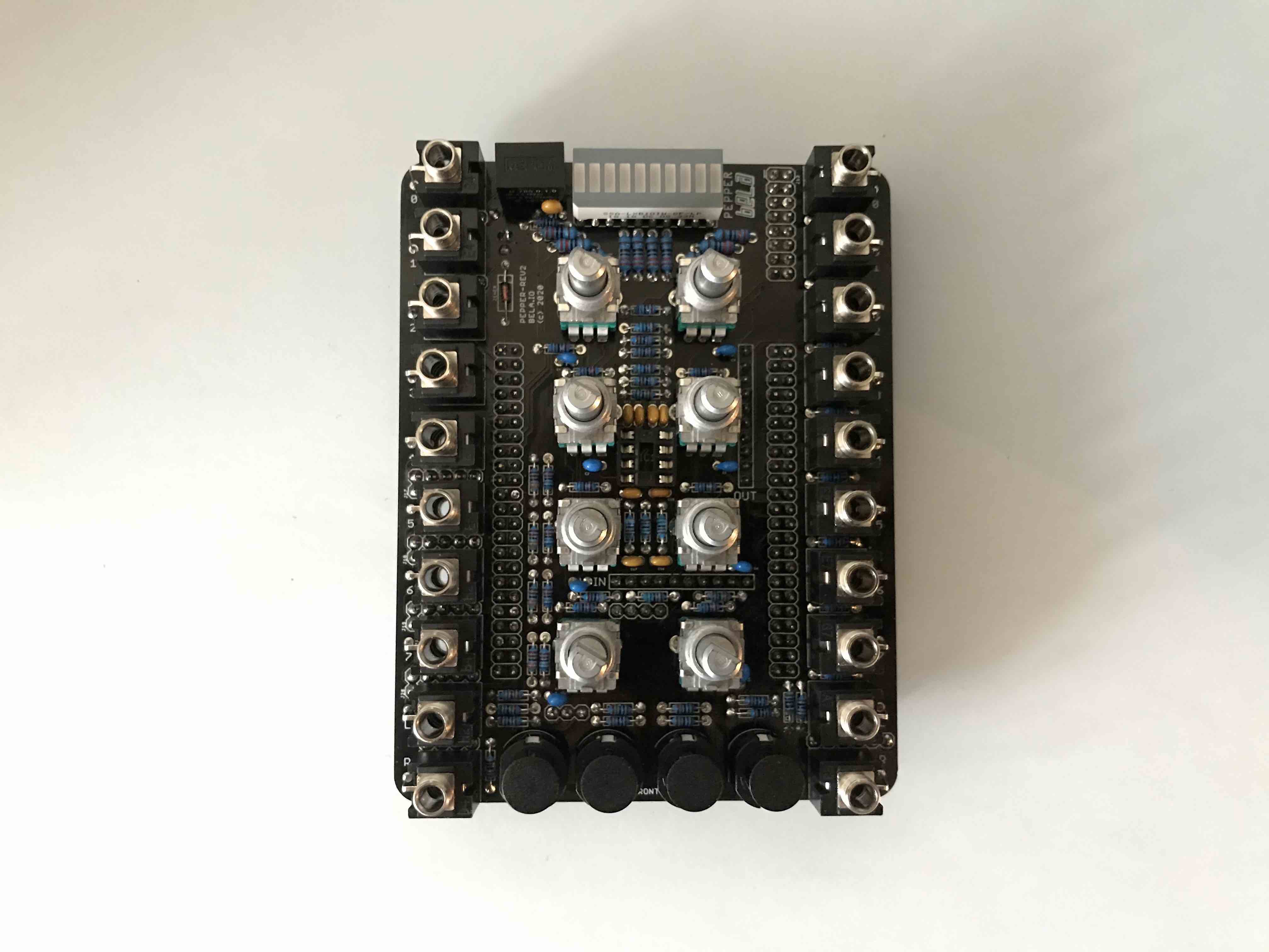
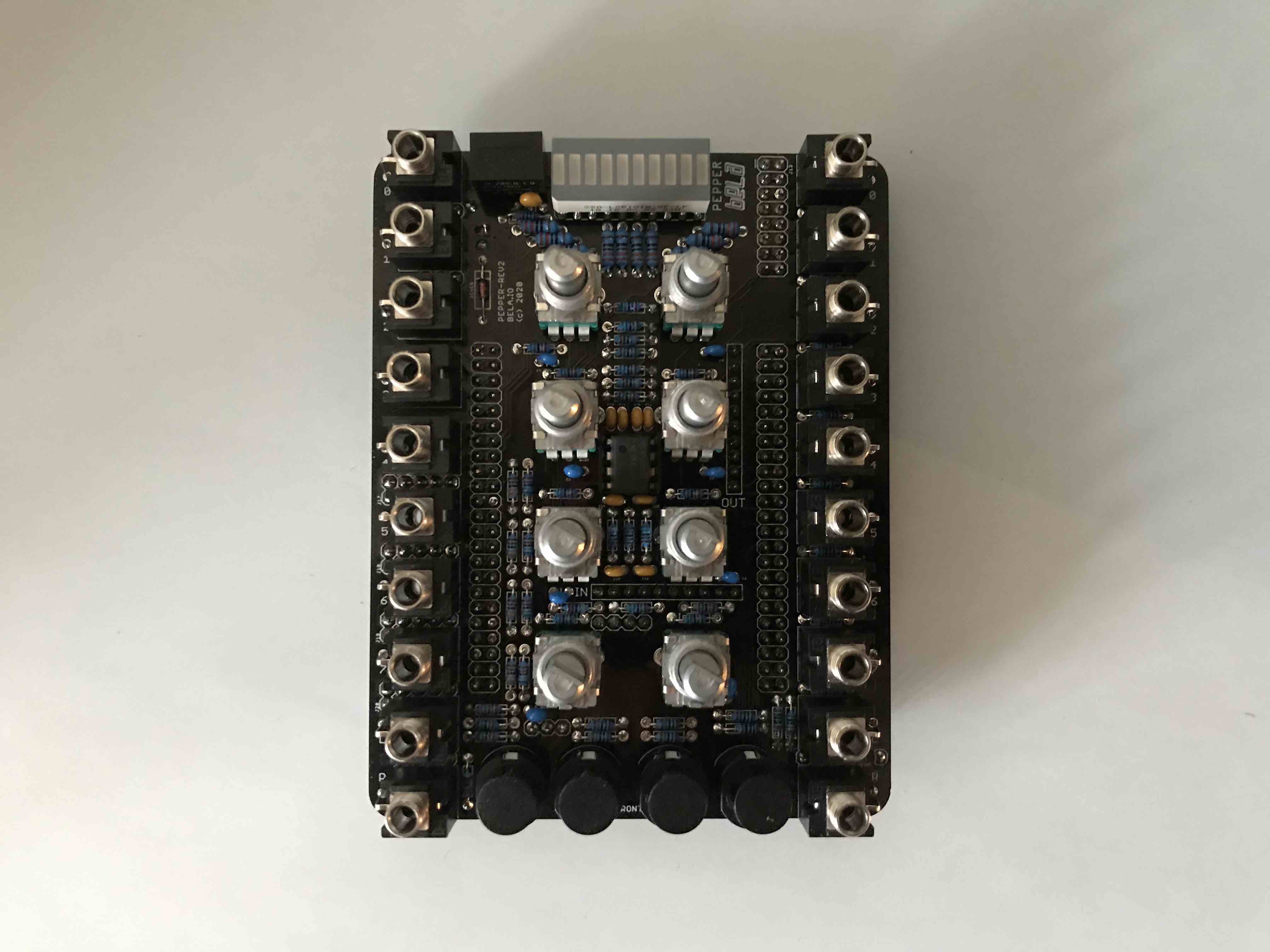
- attach the LED bar graph and ensure the correct orientation by making sure the cut off corner matches the screenprint. To ensure this fits flush with the faceplate insert the component and then attach the faceplate. Tighten a few of the pots and let the LED bar graph fall into place against the faceplate. You should now be able to solder this part with it flush to the back of the faceplate.
- Insert the IC into the cradle.
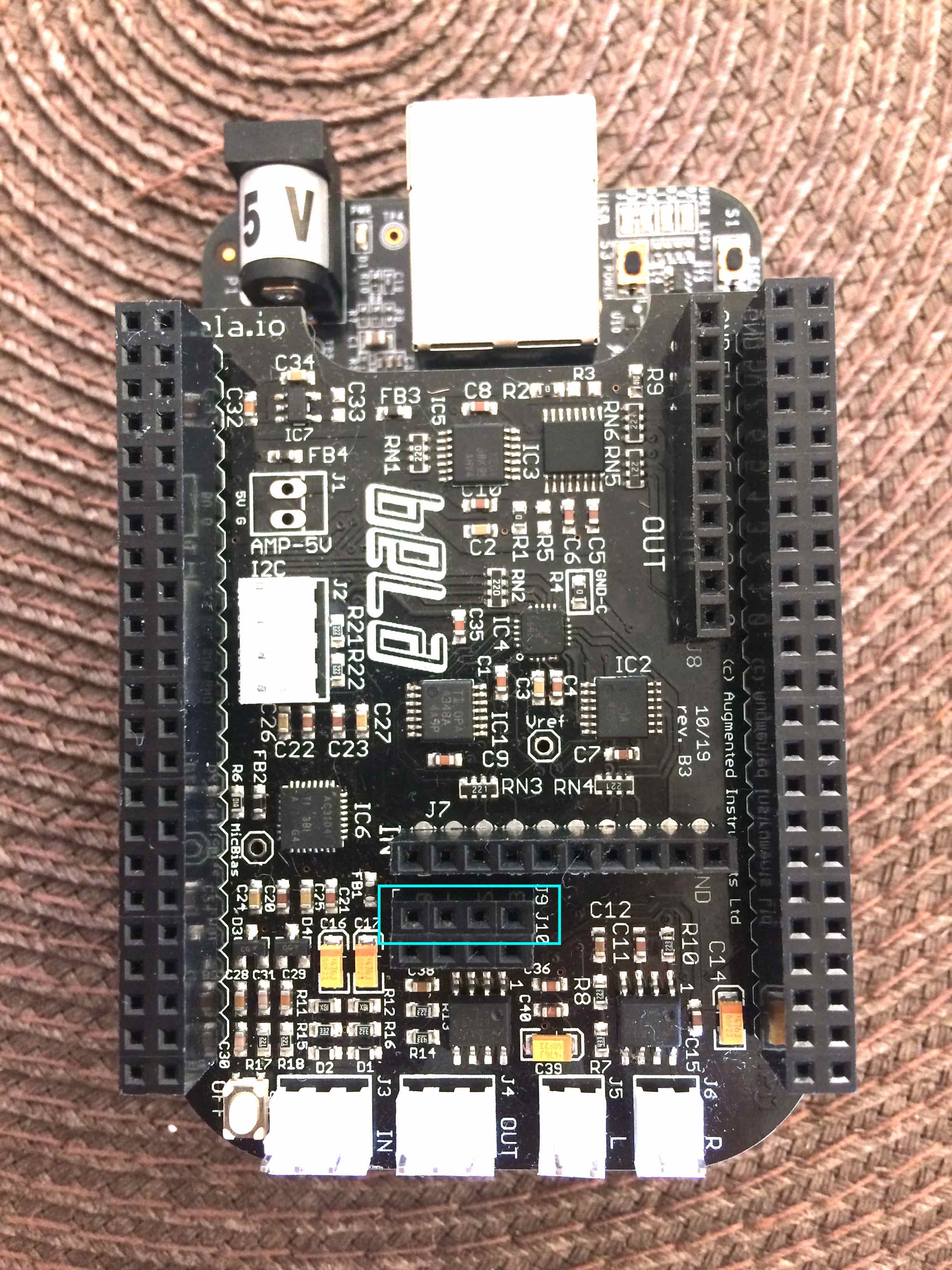
- add a 4-pin female socket header to the line output to the Bela cape (J9). Note that in the below photo there are two rows of 4-pin female headers installed. Only one is required on the row marked J9 but if you only have a 4x2 header then it is fine to install the whole thing. If you have bought the BOM from Mouser you will have a longer strip of female socket headers which it is necessary to cut down. This is easily done with wire cutters but requires sacrificing one of the sockets to get a clean cut (if you want 4 pins, cut at socket number 5).
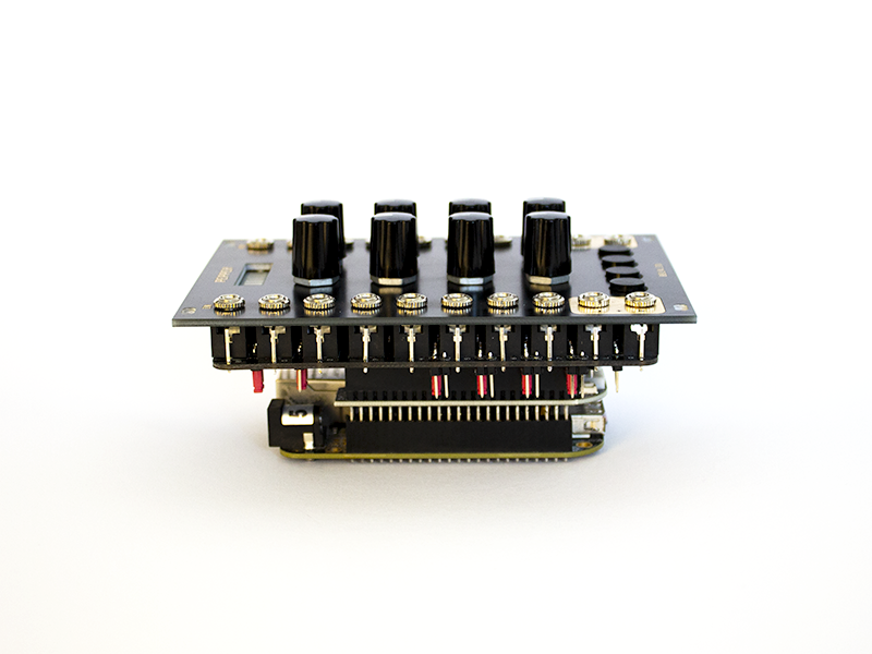
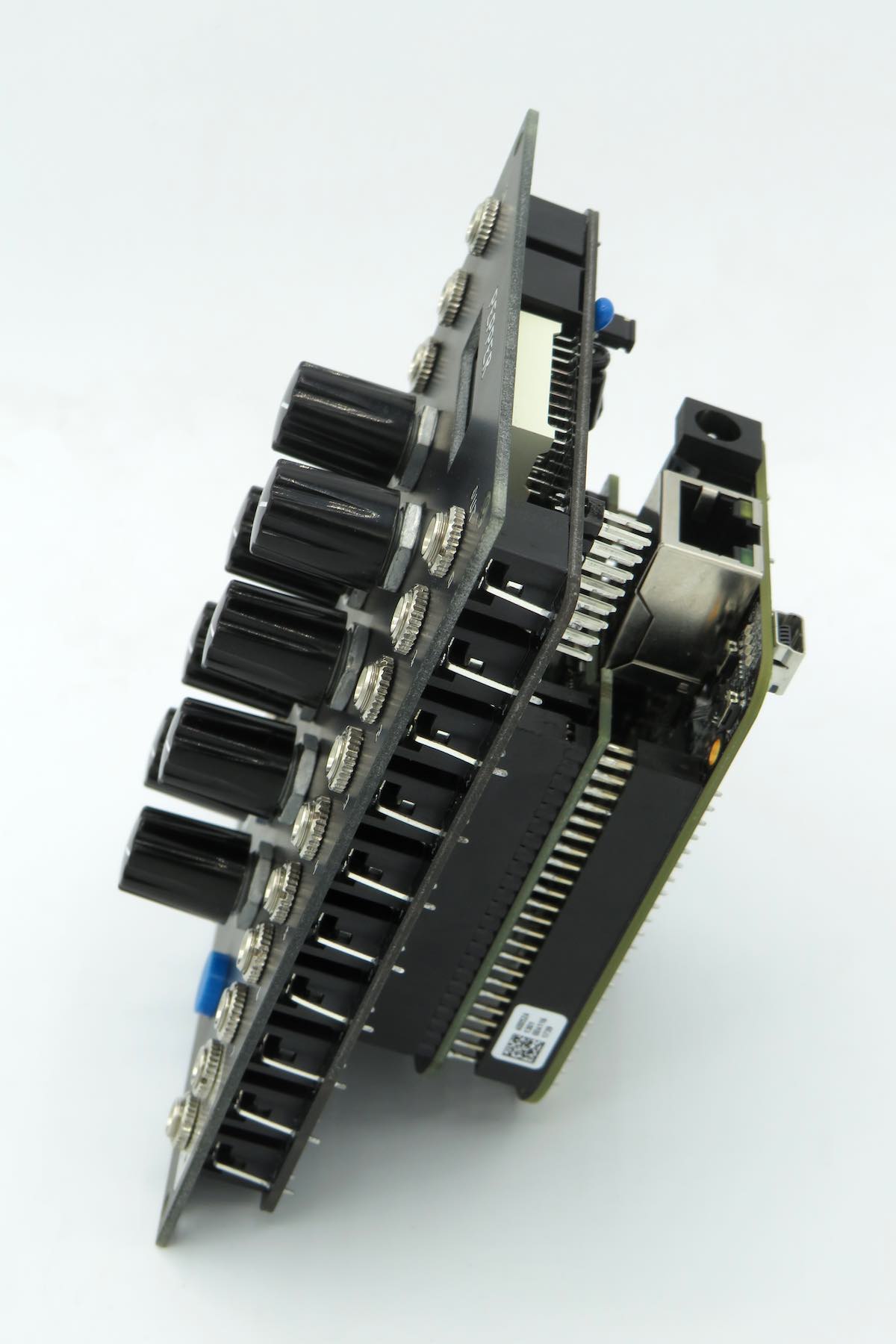
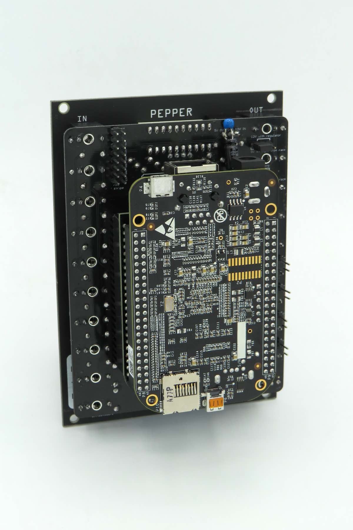
- attach the Bela board with Beaglebone Black to Pepper PCB. Ensure that all the pins are aligned before doing so and push on slowly so as not to bend any pins.
- The final step is to configure the jumpers at the back of the board. See Configuring the board for more details.