LEGACY Building Rev1
Please see the latest build guide: Current Build Guide
This is the build guide for rev1 of Pepper which we stopped shipping in April 2020. If you have a more recent board then please see the Building Rev2 guide.
Before beginning read the notes on choosing resistor values.
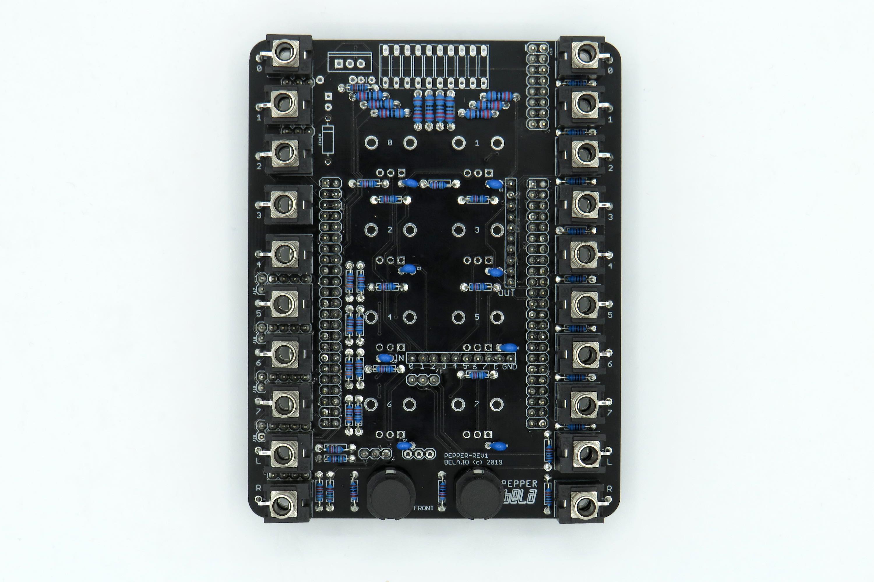
- add resistors R26-R35 (220) for the LED Bargraph

- add resistors R1, R3, R5, R12, R17, R19, R21, R23, R2, R4, R6, R9 (68K) for the voltage dividers.
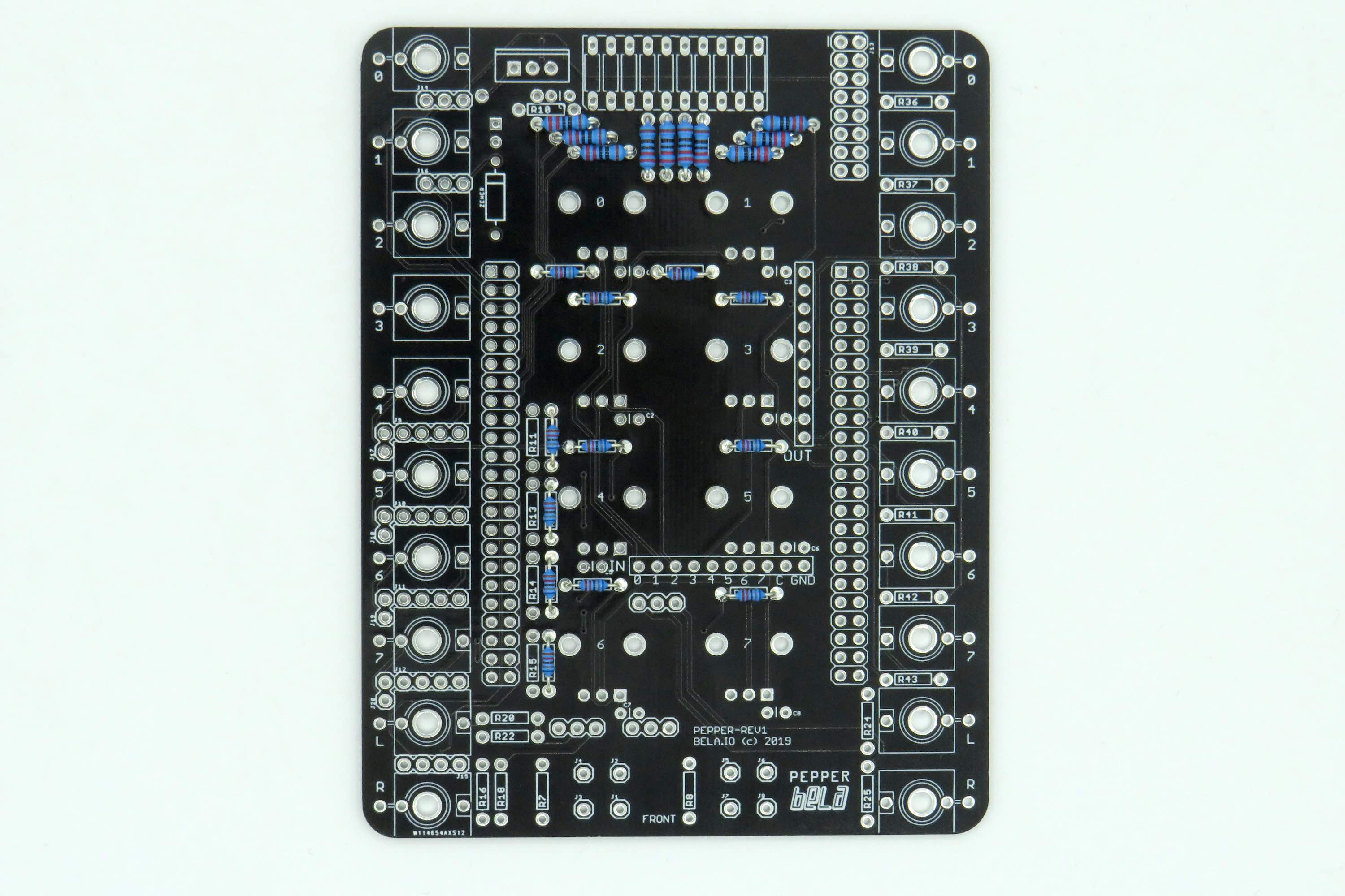
- add resistors R36 - R43 (680) for the analog outputs.
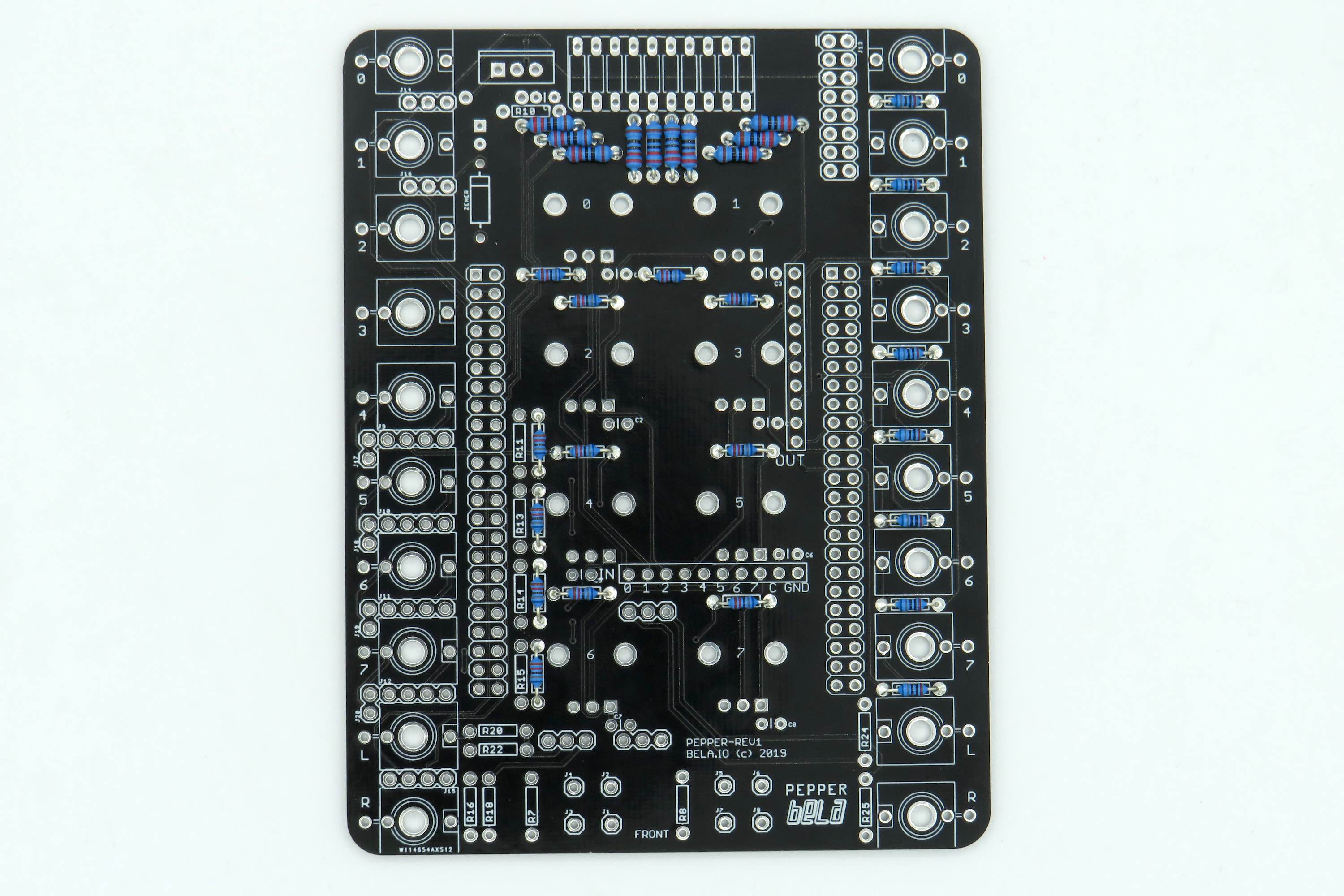
- add the rest of the resistors
- for audio input R16, R20 (82K) and R18, R22 (15K)
- for audio output R24, R25 (1K)
- for the regulator R10 (1K)
- for the buttons R7, R8 (10K)
- for the digital part of the voltage dividers R11, R13, R14, R15 (33K)

- add the 150pF capacitors

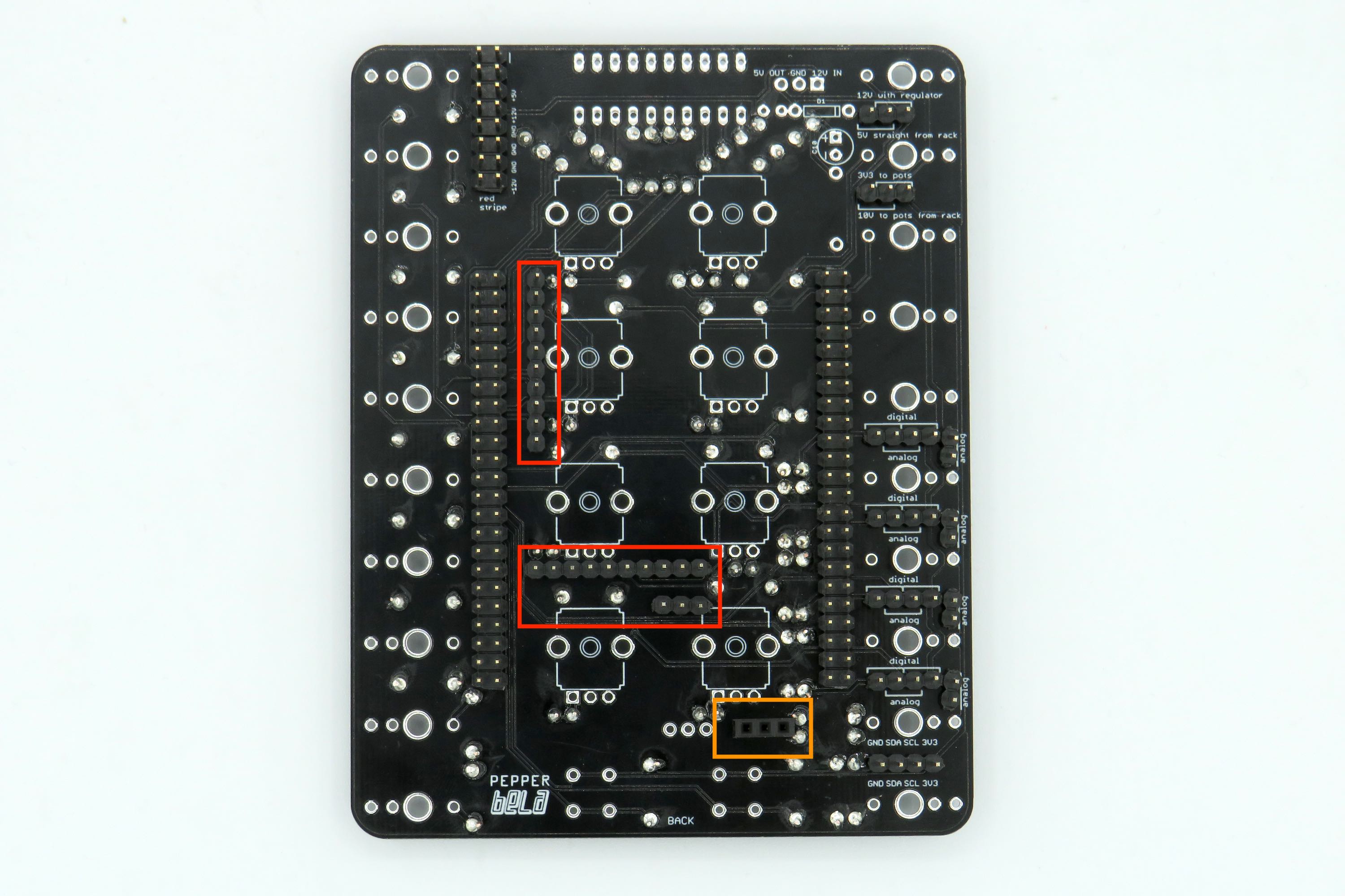
- attach the male and female headers to the board as shown in the image below. It's important that these are attached at a right angle to the board otherwise you'll have problems getting the Bela board to fit on top.
- Tip 1 - use a breadboard to hold the pins upright and place the board on top to solder
- Tip 2 – for single row headers, solder a single pin, and then use your fingers to position the header correctly while heating the soldered pin with the iron.
NOTE 1: it is recommended that you use the slightly longer pin headers (8mm) on the two rows of 10 that make contact with the analog input and output of Bela and the row of three pins that connects to the line out of Bela. If you don't have longer headers then normal sized pin headers (6mm) will suffice but you need to make sure that the cape and PCB and pushed together very tightly.
NOTE 2: depending on your rails it might be a tight fit if you solder in the full 16 pin power connection. If you know you will run the module off of 12V then you can just solder pins to the bottom 10 pins of the power connection to make fitting into your rack easier.
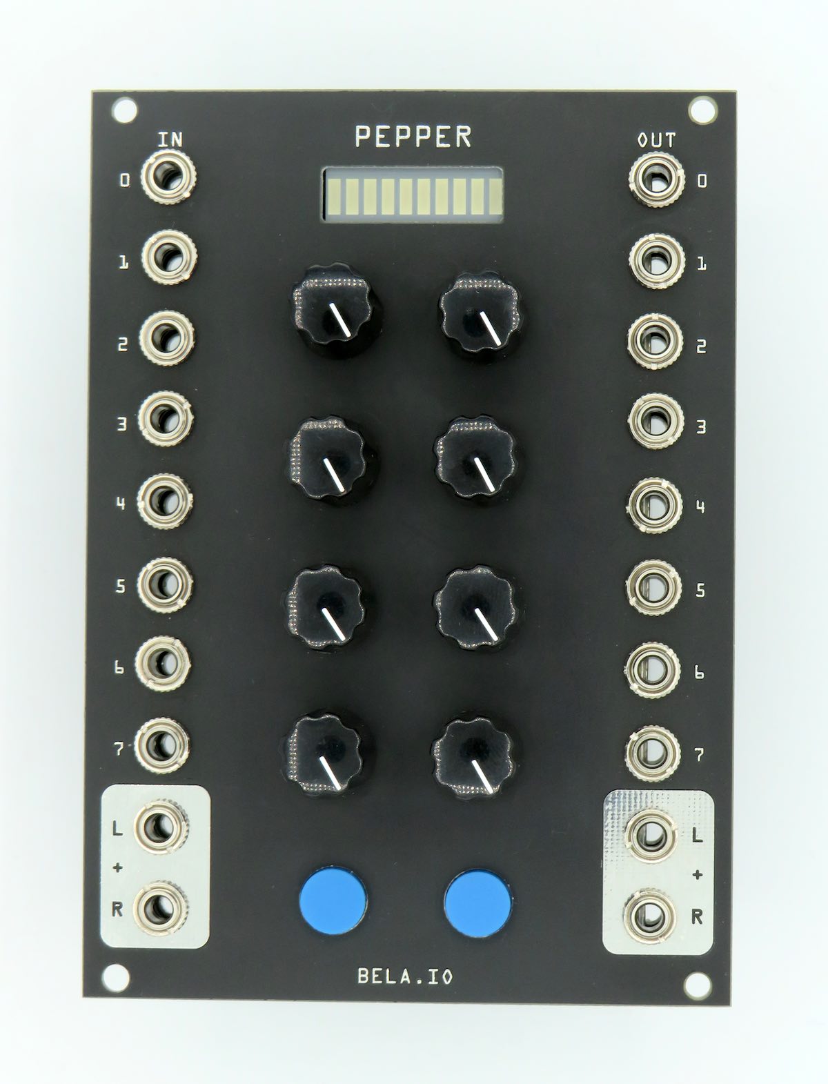
- attach the 3.5m sockets. Before soldering place the faceplate over the sockets to ensure correct alignment and height once the module is complete and the faceplate has been added.

- attach the two buttons. Make sure these fit flush to the PCB to avoid any alignment issues when fitting the faceplate. The flat edge of the plastic casting should face to the left when you look at it as show in the picture below.
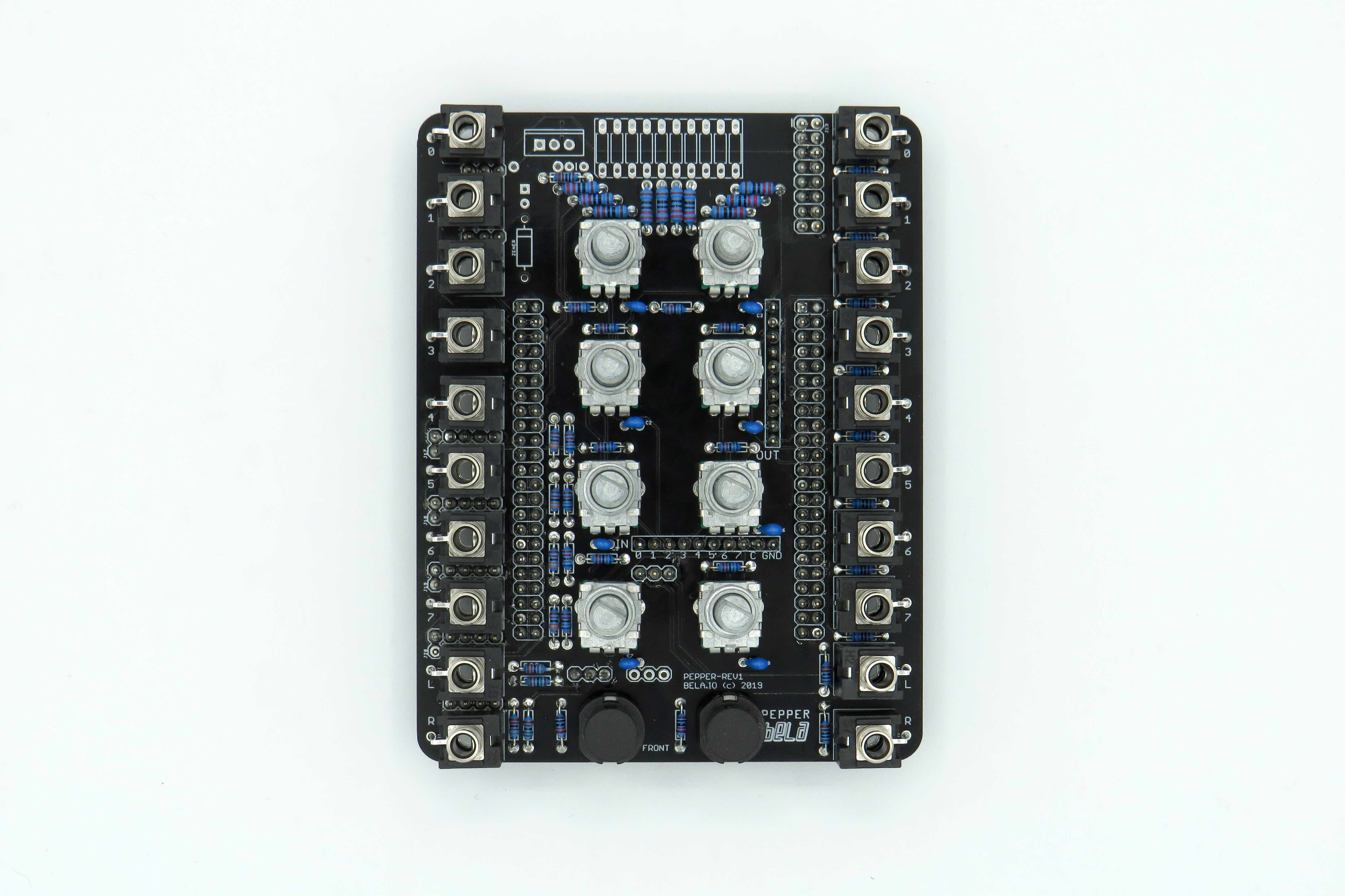
- attach the 8 50K potentiometers. Before soldering in side supports check alignment with the faceplate. Cut lugs on the top of the pot if necessary.
- attach the flyback diode and electrolytic capacitor to the back of the PCB. Make sure you get the polarity of both correct!
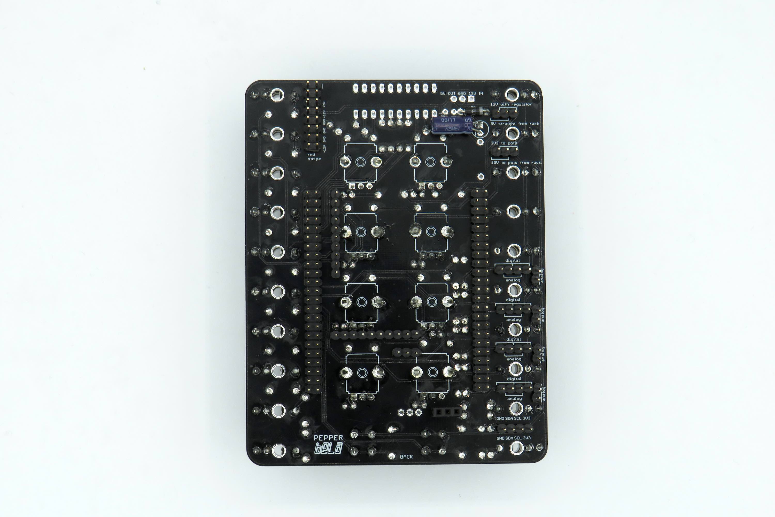
On the other side of the PCB add the final capacitor, zener diode (again make sure to put this in the correct way around) and the regulator. The text of the regulator should face towards the bottom of the PCB.

- attach the LED bar graph and ensure the correct orientation by making sure the cut off corner matches the screenprint. To ensure this fits flush with the faceplate insert the component and then attach the faceplate. Tighten a few of the pots and let the LED bar graph fall into place against the faceplate. You should now be able to solder this part with it flush to the back of the faceplate.

- add the female header to the line output to the Bela cape.

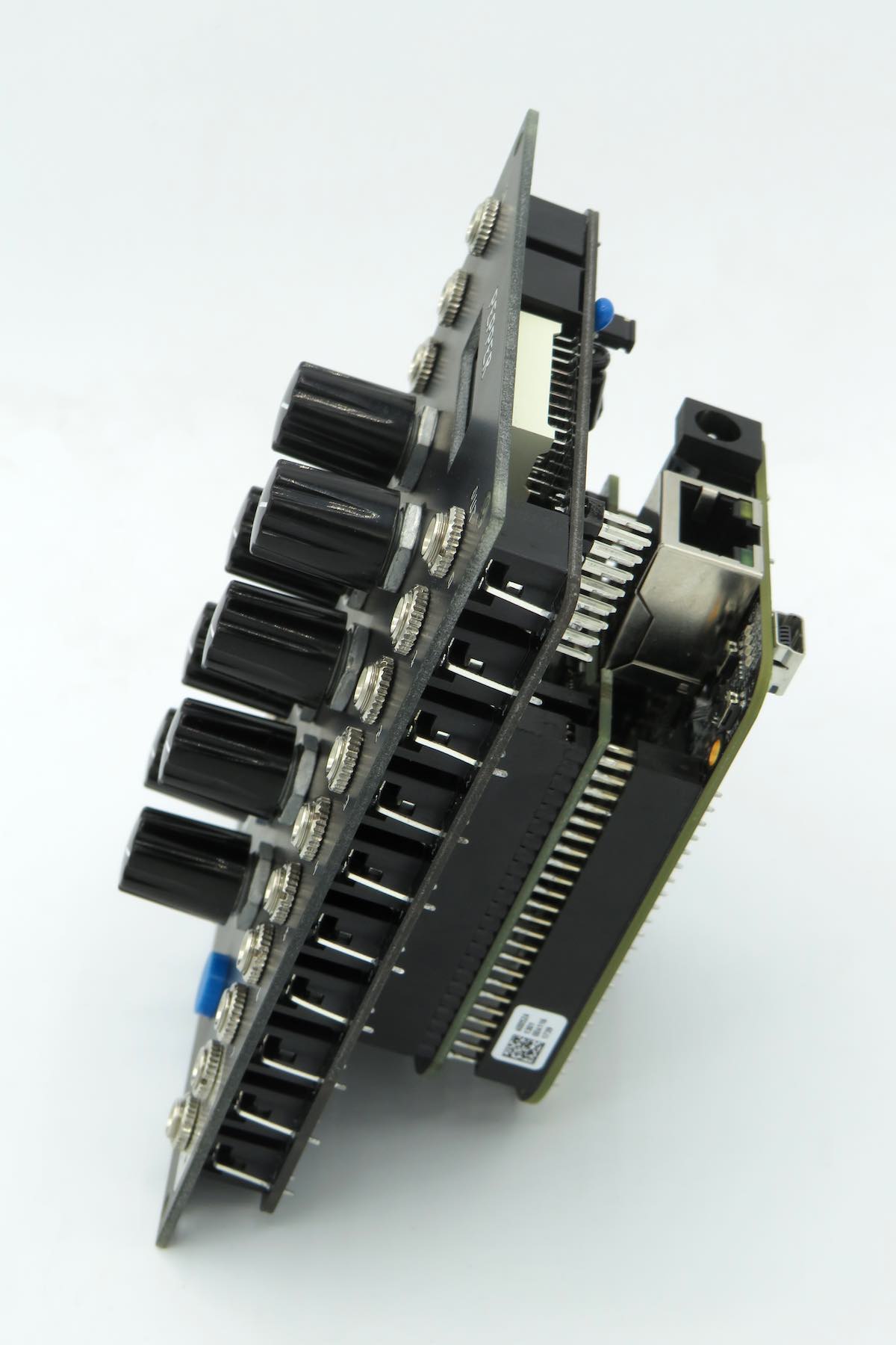
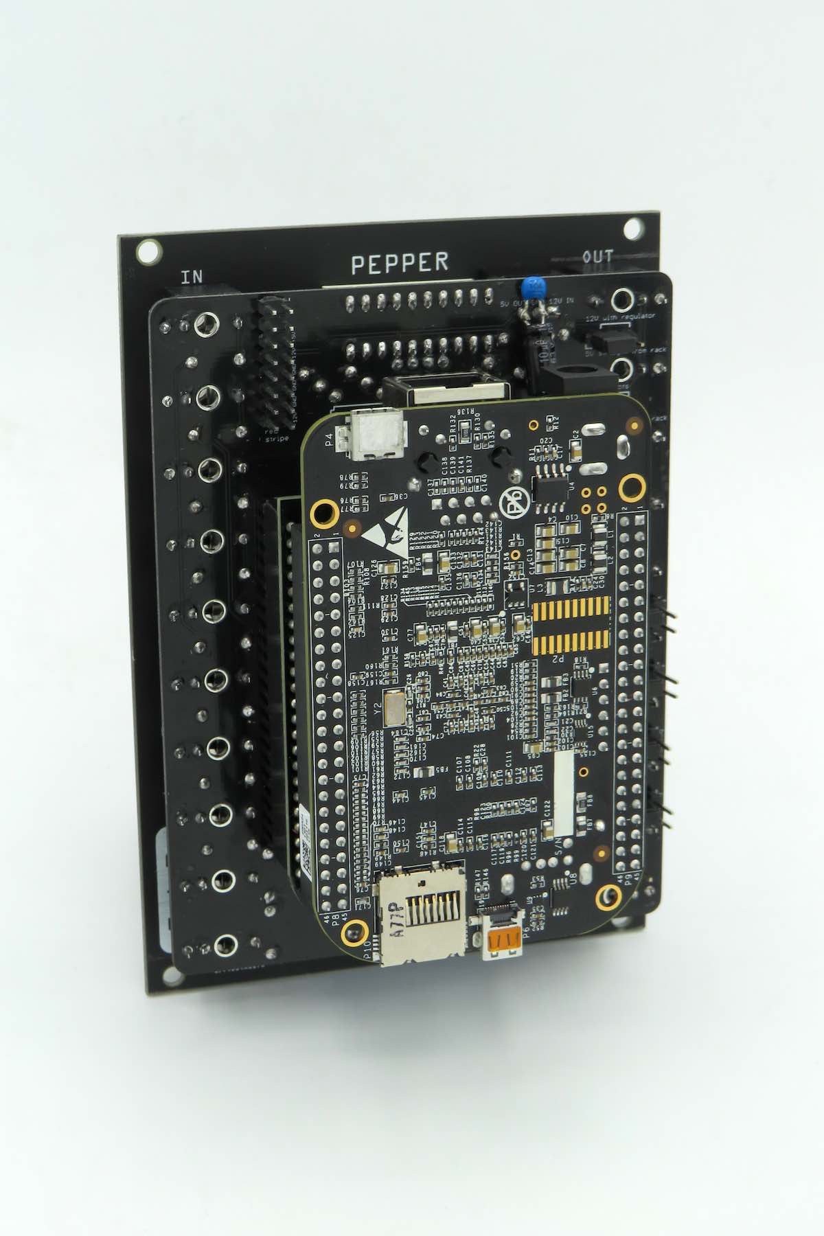
- attach the Bela board with Beaglebone Black to Pepper PCB. Ensure that all the pins are aligned before doing so and push on slowly so as not to bend any pins.
The final set is to configure the jumpers at the back of the board. See Configuring the board for more details.
