Object Oriented Design UML Diagram
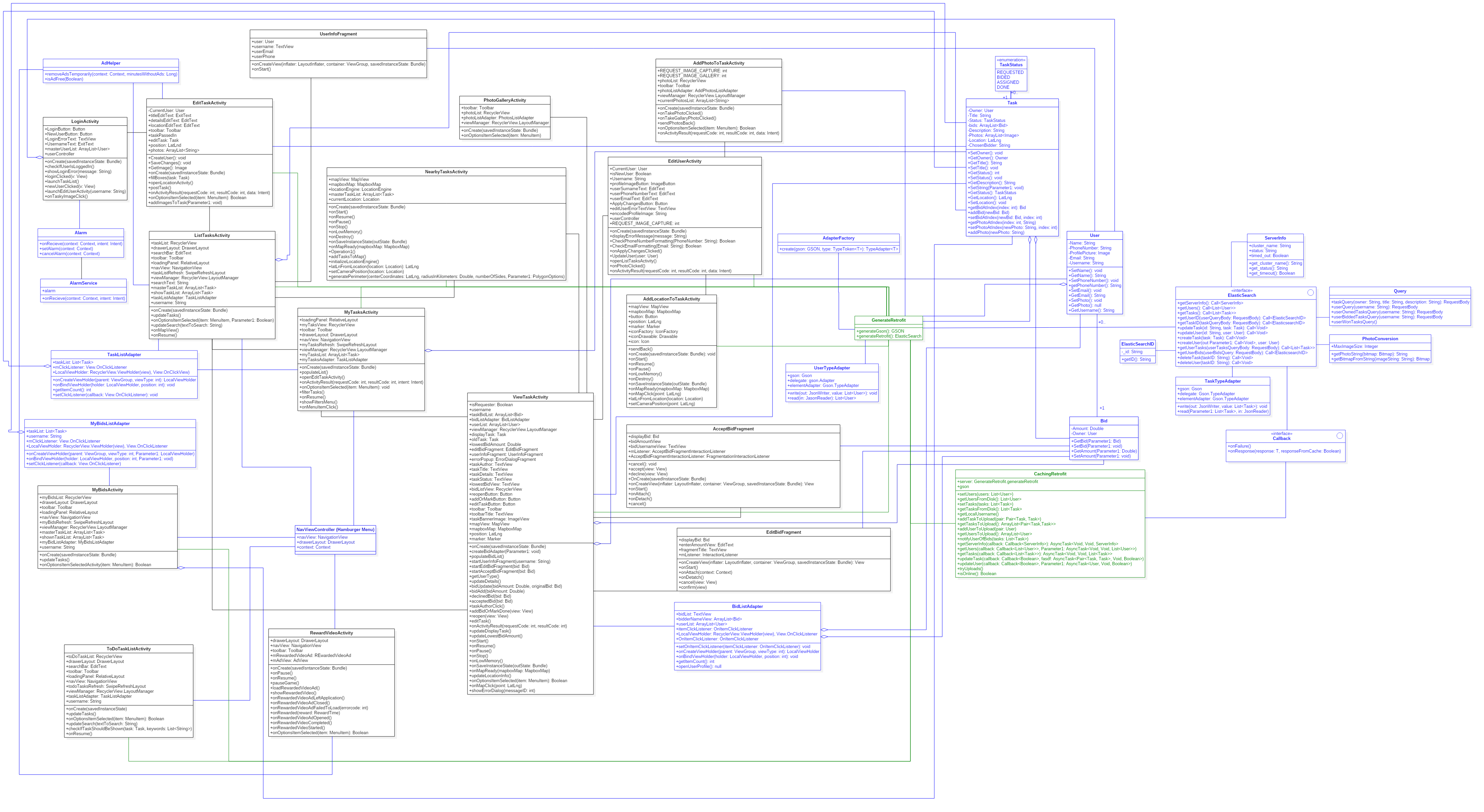
Below is a legend that needs to be followed for the UML. Due to the complexity of the UML, some color codes were added in to help disambiguate overlapping file paths.
- Black: Activities and connections between activities
- Blue: Models, Utilities, Controllers, Exceptions, and Adapters as well as any links to these
- Green: Any links to the two classes GenerateRetrofit and CachingRetrofit, as these classes had connections to almost everything and cluttered up everything massively
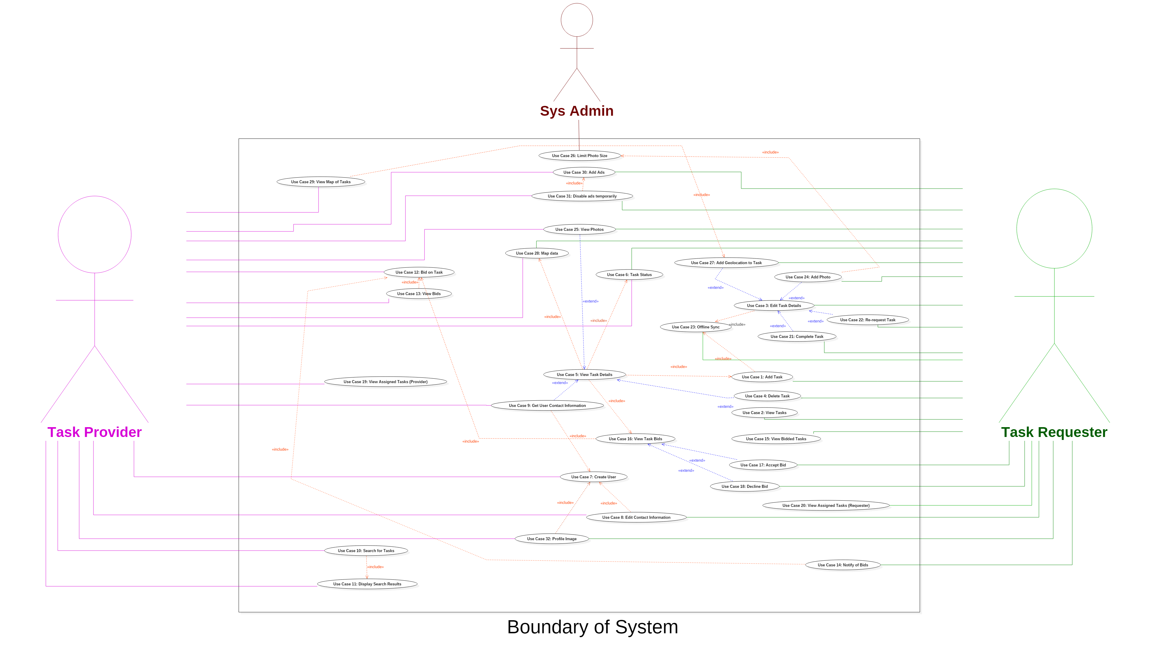
Below is a legend of the color codes used to distinguish the relationships between use cases and actors.
- Green: Participation of Task Requester in a use case.
- Pink: Participation of Task Provider in a use case.
- Red: Participation of Sys Admin in a use case.
- Blue: Inclusion of a use case.
- Orange: Extension of a use case.