UART ESP v1 Code Flashing
Programming / Flashing USB UART Control
In order to ease programming on the earlier CWX v1, a simple two transistor circuit is added to our boards which when connected to a USB to UART module, allows the host computer to control the DTR = Reset, and RTS = Boot Mode. This makes recompiling and flashing so much simpler.

Note:
This UART Cable will also power the SDK board from the UARTs 3V3. Some boards may not function fully (such as the RMIS as it needs 3V3 and 5v), but at least you can program / flash / test your code.
Remember, if using the CWX SDK board, do NOT connect the 3V Lithium battery as well as the UART cable.
What is in the box
Our UART programming cable kit, includes the UART and a header cable. This cable has two 6 pin headers. You only need one 6 pin header connector, so the other should be cut off. You could alternatively cut the cable in two and use it to make another cable assembly.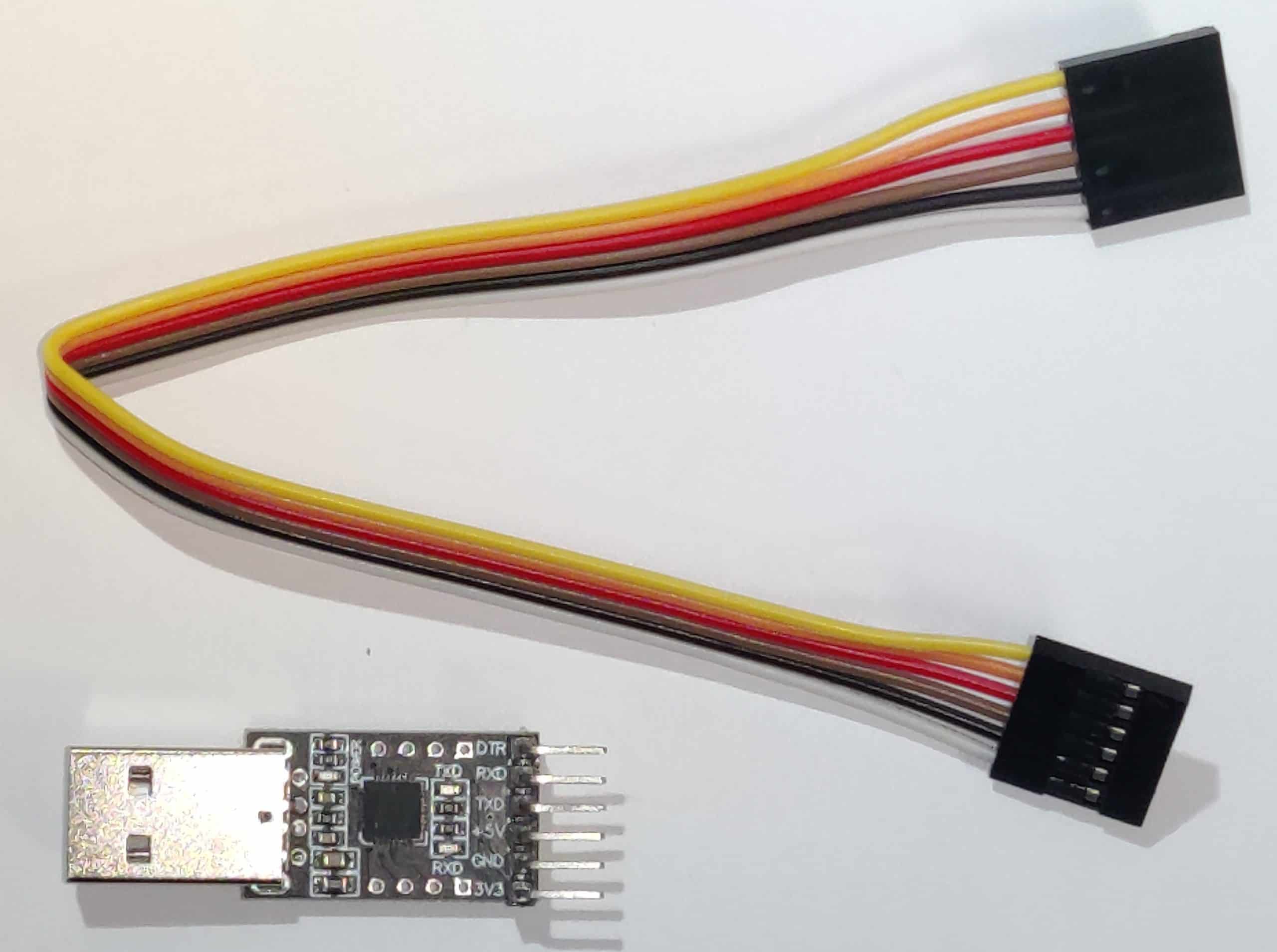
UART
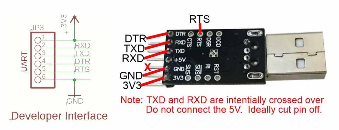
Our USB to UART module has both of these RTS and DTR connections.
UART Connections to the Developer Interface on our SDK Boards.
Note:
- The 6 way cable looms that are provided may not follow the same colours as in the below photo examples. Please check the connections carefully!
- Do not plug the 6 way header into the CWX and into the UART. These connections will NOT work and could damage the UART and/or the SDK board.
Cable connection examples
The below information shows the connections required. Once the loom is created, it can be used for all our boards.
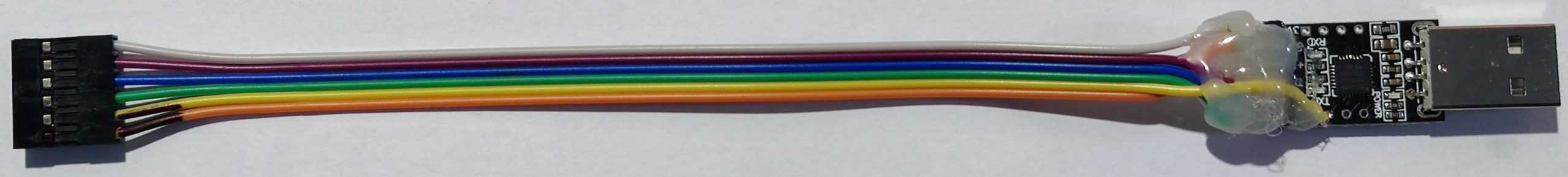
Cable Soldered into a complete loom

Connections UART end
Note that this photo shows the 5V pin intact. As we only need the 3V3, you maybe best (but optionally), cut this off to prevent accidental shorts.

For speed, glue from heat gun has been added to protect and strengthen the connections.
If heat shrink available, then this would more ideal and make for a neater cable but either option is good in order to save accidental shorts and help protect the wires from breaking.

To make it easier, and safer, to help remember which way the connector is plugged into the developer interface, it would be ideal to mark the cable to indicate the 3V3 positive or ground end.
Completed UART Cable Loom
Additional information, and other technical details on this project, maybe found in the related repository pages.
Repository Folders
- Code (Code examples for Arduino IDE and PlatformIO)
- Datasheets and Information (Component Datasheets, Schematics, Board Layouts, Photos, Technical Documentation)
- Certification (Related Repository Project or Part, Certification Information)
Repository Tabs
- Wiki (Related Repository Wiki pages and Technical User Information)
- Discussions (Related Repository User Discussion Forum)
- Issues (Related Repository Technical Issues and Fixes)
We value our Customers, Users of our designs and STEM Communities, all over the World . Should you have any other questions, or feedback to share to others, please feel free to:
- Visit the related Project plus the related Discussions and Wiki Pages. See tab in each separate repository.
- Project Community Information can be found at https://www.hackster.io/DitroniX
- DitroniX.net Website - Contact Us
- Twitter: https://twitter.com/DitroniX
- Supporting the STEM Projects - BuyMeACoffee
- LinkedIN: https://www.linkedin.com/in/g8puo/
Dave Williams, Eastbourne, UK.
Electronics Engineer | Software Developer | R&D Support | RF Engineering | Product Certification and Testing | STEM Ambassador
Supporting STEM Learning
Life is one long exciting learning curve, help others by setting the seed to knowledge.