Lab 05 old
For this week’s lab, we will be building a useless box; this is a project inspired by Make Magazine, which you used as reference for the preLab, and a similar lab at Stanford's ENGR40m. We will use this lab to help you to experiment with digital fabrication tools. The methods that will be used are 3D printing and laser cutting.
To submit your lab, clone this repository -- and include all files / images / code that is requested!

3D print this servo mount:
- Download and install Makerbot Print.
- Create a MakerBot account.
- Start the Makerbot Print Application and log in.
- On this this page, download all files.
- Import the
.stlfile from the files you downloaded into the printer software. - Make sure the orientation of your part makes sense. What orientation makes the most sense for 3D printing?
- Turn off the raft. There is no need to print a raft for this part.
- Connect your laptop to the printer over USB, or via WiFi. Ask any member of the teaching team for WiFi credentials.
- Once the Printer is connected hit "print".
- After the printer has started the USB cable can be disconnected from your laptop.
An option for making the "bopper":
- Create a free education OnShape account using your student email.
- Do the sketching tutorial and part design tutorial to learn the basics of Computer Aided Design (CAD) on OnShape.
- Create a bopper to 3D print.
Laser cut cardboard to make your useless box in the Maker Lab.
- Download a vector editing program like Inkscape (free) or Adobe Illustrator (free for 30 day trial).
- Open the laser cutter template file for the useless box in your vector editing program.
- Modify the vector drawing to have a personal touch, and holes for the servo mount, switch, and Arduino wires. Make sure the all lines that you want the printer to recognize are 0.001pt thick and the proper color (black for cutting). Save your file. BONUS: include lines or images that you don't plan to cut all the way through to experiment with etching.
- To laser cut, open your modified file in Adobe Illustrator on the lab’s computer. Look around the laser cutting room for instructions, reference sheets, and scrap materials. The step by step instructions are attached on the suction system to the left of the computer.
- Keeping in mind Niti's safety instructions, follow the instructions to cut (these are summarized for our purposes):
- Load the machine with the 5/32" thick cardboard we provided. If the material is bent, tape the ends using duct tape to the sides of the printing bed to make it as flat as possible.
- Disable X/Y.
- Move the laser to its starting position on top left corner of the material.
- Focus the laser using the focus tool and up and down arrows. Flip the focus tool up again after you're done.
- Press the set home button.
- Close the lid.
- Open the printer preferences.
- Make sure you set the different power levels for the cut values pertaining to the material you're using. For the cardboard we are providing, the values should be: Speed 45%, Power 70%, and Frequency: 500Hz. On the same window, adjust the printing bed size to 24" horizontal, and 18" vertical. When you save the settings, make sure the image on the preview is well positioned (not too close to the edges and fitting well in the space). Press print.
- Turn on the air assist compressor on the floor on.
- Turn the suction system, the big blue box, on.
- Print the job on the computer.
- Find the job you're printing on the laser cutter, and press 'go'.
- Assemble the parts, once the configuration makes sense, hot glue them together. Tip: don't hot glue the part where you'll attach the servo until you've attached the servo!
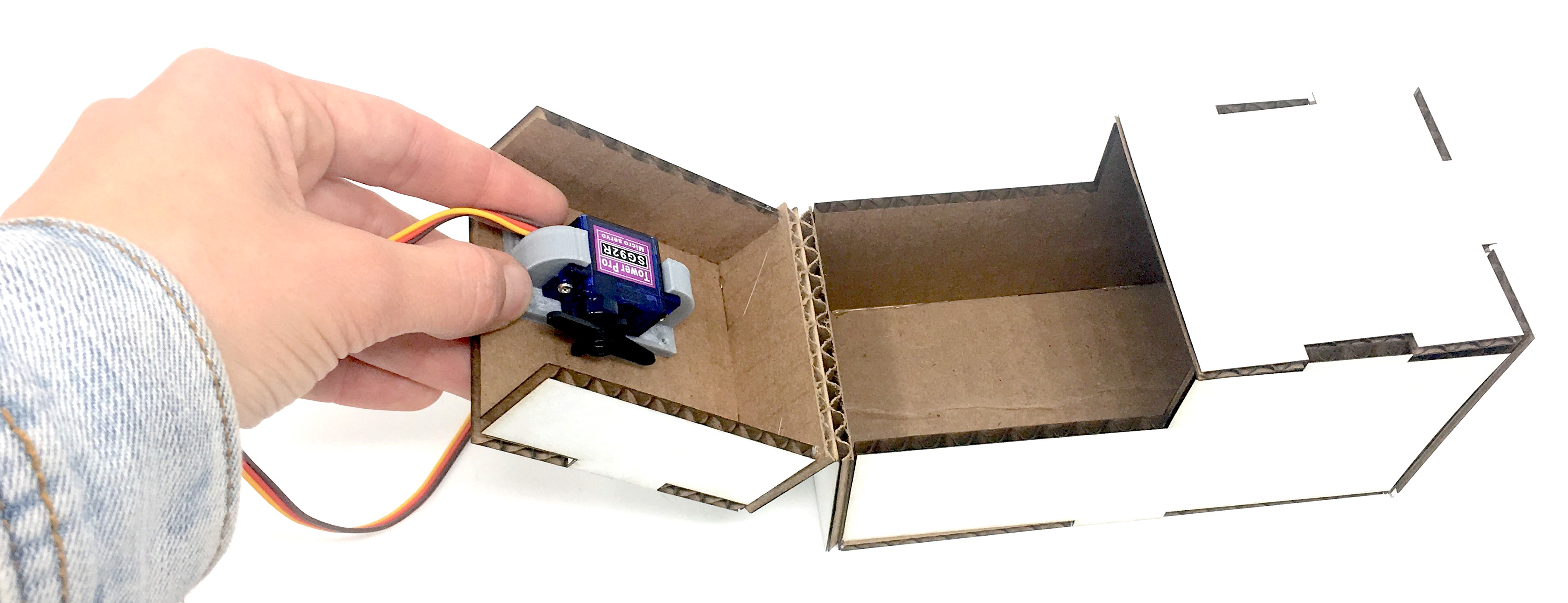 What seems off in this image?
An option for making the "bopper": Now that you know how to use the laser cutter, draw something on the vector software to use as the "bopper" — there are a lot of cool scrap materials available on the scrap pile, like acrylics that will work well for this. Make sure to adjust the speed, power, and frequency settings for the material you decide to use.
Create a circuit to connect your 9 volt power supply, toggle switch and servo to the metro mini. You can use this one or one you design on your own.

Pick up a 9V connector and a battery from the cart. The red wire from the connector should go to Vin on the Metro Mini, and the black wire should go to Ground.
Pick up a toggle switch from the cart. You might notice that this part is not breadboard-able. That is because it is a panel mount part; you can see from the threaded part at the base of the toggle that the whole device is meant to be mounted to the front of a panel, with just the toggle part and a washer and nut sticking out.
On the back of the toggle switch, there are 2 sets of 3 tabs/blades with holes. You will need to solder on jumper wires to the tabs (only one side is necessary) to connect it to your circuit.
Once you have the circuit working, you can move your circuit to a protoboard from your breadboard. (You'll want to make a socket with female connectors for the Metro Mini & servo.) This can make things smaller and more compact, and also make the connections more robust.
Load either of the examples below to your Arduino, and see how they work. Try to modify the behavior in a way that will make it your own.
The first example simply polls the state of the switch in the main loop and triggers actions if it notices the switch state has changed.
The second example sets an interrupt on the input pin the switch is attached to, letting the processor call a registered interrupt service routine (function) when it changes. In this example the main loop is not required to do anything at all, though we can use it to output some state information to the serial console for fun.
Think about where each component should go, and assemble your useless box so that it works like the one on the video you saw for the preLab. Insert the electronics, install the mechanical components, glue anything that has not been glued yet, and test your useless box!
For your write up, include:
- Your Arduino code.
-
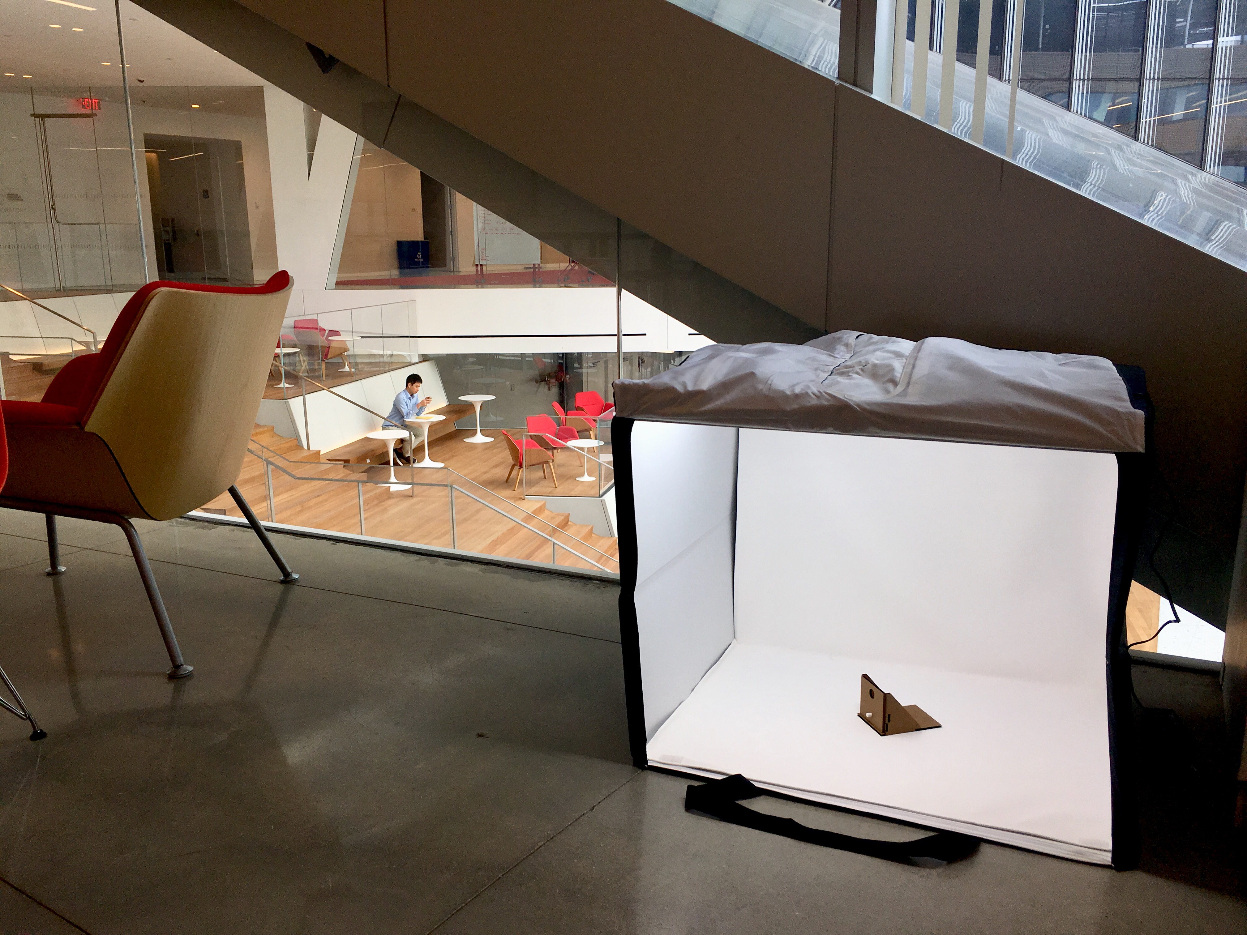
.stlor.svgfiles for your "bopper" — if you use some other technique, include the respective supporting material. - At least one photo of your useless box taken in the MakerLab's Portable Photo Studio (or somewhere else, but of similar quality).
- A video of your useless box in action.
General resources: