Alternate forwarding planes: VPP
This tutorial is a step-by-step guide showing how to build a high-performance software router using two complementary open source projects: VPP and FRRouting.
VPP is a feature rich, high-performance packet processing platform that runs on commodity hardware. VPP leverages DPDK[1] and runs as a Linux user-space application, moving the routing/forwarding of packets out of the Linux kernel.
FRRouting (FRR) is a multi-platform routing stack that provides implementations for BGP, OSPF, IS-IS, EIGRP, RIP, LDP, PIM and NHRP. FRR is a fork of Quagga.
More information about VPP and FRRouting can be found in [2] and [3].
This tutorial explains how to integrate the two projects together. In other words, how to build a router using FRR for the control plane and VPP for the data-plane. For this to work, we're going to use VPP's router plugin [4], which acts as a glue between VPP and any Linux-based routing stack. This plugin implements logic to punt control packets to the Linux network stack so routing daemons can work. Also, it implements a netlink-based mechanism that continually synchronizes the Linux's kernel routing table into VPP's FIB (the fast-path).
This section explains how to install VPP (with all the required plugins) and FRR.
For simplicity sake, we're going to build and install everything in a Vagrant VM provided in the VPP repository.
Before proceeding, make sure that the host operating system has the following software installed:
- Git: https://git-scm.com/book/en/v2/Getting-Started-Installing-Git
- VirtualBox: https://www.virtualbox.org/manual/ch01.html
- Vagrant: https://docs.vagrantup.com/v2/installation/index.html
1 - Clone the VPP repository(the latest vpp version 18.04 can work fine with vppsb) and create the Vagrant guest machine (this can take some time):
$ git clone https://gerrit.fd.io/r/vpp
$ cd vpp/build-root/vagrant/
$ export VPP_VAGRANT_DISTRO=ubuntu1604
$ vagrant up
2 - SSH into the Vagrant VM:
$ vagrant ssh
From now on all commands should be typed in the VM.
3 - Clone the VPPsb repository:
$ cd ~
$ git clone https://gerrit.fd.io/r/vppsb
4 - Build and install VPP with the netlink and router plugins:
$ sudo apt-get install -y python-cffi python-pycparser
$ cd /vpp
$ git checkout v18.10
$ ln -sf /home/vagrant/vppsb/netlink
$ ln -sf /home/vagrant/vppsb/router
$ ln -sf ../../netlink/netlink.mk build-data/packages/
$ ln -sf ../../router/router.mk build-data/packages/
$ cd build-root/
$ ./bootstrap.sh
$ make V=0 PLATFORM=vpp TAG=vpp_debug install-deb netlink-install router-install
$ sudo dpkg -i *.deb
$ sudo ln -sf \
        /vpp/build-root/install-vpp_debug-native/router/lib64/router.so.0.0.0 \
        /usr/lib/vpp_plugins/router.so
5 - Edit the default configuration file (/etc/vpp/startup.conf) as follows:
unix {
  nodaemon
  log /tmp/vpp.log
  cli-listen /run/vpp/cli.sock
  full-coredump
}

api-trace {
  on
}

api-segment {
  gid vpp
}
To test if the installation went ok, restart VPP with the following command:
$ sudo service vpp restart
In another shell, type the following:
$ sudo vppctl enable tap-inject
If both commands are executed without any errors, it means that VPP and the router plugin were installed successfully.
The following commands will install all FRR dependencies and then FRR itself using a standalone deb package:
$ sudo apt-get install iproute2 libc-ares2
$ cd ~
$ wget https://github.com/FRRouting/frr/releases/download/frr-3.0.3/frr_3.0.3-1_ubuntu16.04.1_amd64.deb
$ sudo dpkg -i frr*.deb
In this test we're going to use the GNS3 network simulator to set up the following topology:
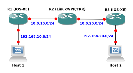
In this topology, R1 and R3 are standard Cisco IOS-XE virtual routers. Any other virtual router can be used as long as it supports OSPFv2 (e.g. Juniper vMX). R2 is our VPP VM with FRR installed.
The goal is to set up OSPF in the network and then use the iperf traffic generator in the hosts to confirm that VPP (the fast-path) is being used in R2 to route the data packets.
Open GNS3 and add a VirtualBox template for the VPP VM we created earlier. In the Network tab, specify that this VM should have 5 network adapters by default as shown in the image below:
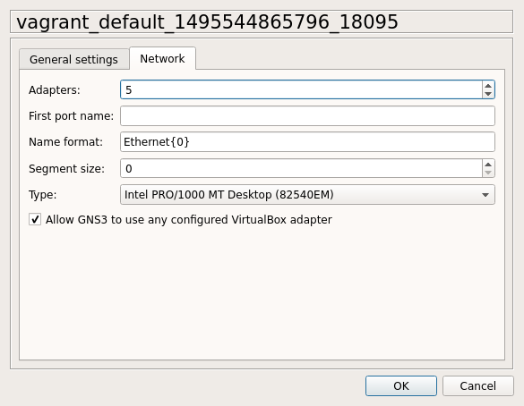
In the GNS3 topology, use VPP's g3 interface to connect to R1 and VPP's g4 interface to connect to R2.
The first thing to do is to edit the dpdk section of the /etc/vpp/startup.conf file and specify the two interfaces we want to use with VPP. Example:
dpdk {
  dev 0000:00:0a.0
  dev 0000:00:10.0
}
We need to use the PCI ID of the NICs and not their Linux interface names. To map interface names to PCI IDs, we can use the following command:
# sudo lshw -class network -businfo
Bus info          Device     Class      Description
===================================================
pci@0000:00:03.0  enp0s3     network    82540EM Gigabit Ethernet Controller
pci@0000:00:08.0  enp0s8     network    82540EM Gigabit Ethernet Controller
pci@0000:00:09.0  enp0s9     network    82540EM Gigabit Ethernet Controller
pci@0000:00:0a.0  enp0s10    network    82540EM Gigabit Ethernet Controller
pci@0000:00:10.0  enp0s16    network    82540EM Gigabit Ethernet Controller
For this particular test, put the last two devices in the VPP configuration file. Also, make sure that the two associated Linux interfaces are administratively down:
# ifconfig enp0s10 down
# ifconfig enp0s16 down
Now restart VPP for the changes to take effect:
# service vpp restart
If everything went right, the interfaces we specified in the configuration file should disappear from the Linux kernel network stack. DPDK owns them now.
Note: VPP is generally used in conjunction with DPDK in order to have direct access to the NICs, bypassing the Linux network stack. VPP also supports two non-DPDK drivers, namely veth and tun, to enable use inside network namespaces. More information about using VPP with network namespaces can be found in [7].
Now configure the VPP data-plane interfaces:
# vppctl create loopback interface
# vppctl set interface state loop0 up
# vppctl set interface state GigabitEthernet0/a/0 up
# vppctl set interface state GigabitEthernet0/10/0 up
# vppctl set interface ip address loop0 172.16.0.2/32
# vppctl set interface ip address GigabitEthernet0/a/0 10.0.10.2/24
# vppctl set interface ip address GigabitEthernet0/10/0 10.0.20.2/24
Enable the router plugin with the following command:
# vppctl enable tap-inject
This command will create a Linux tap interface for each VPP data-plane interface. These tap interfaces are basically a bidirectional communication channel between VPP and the Linux network stack. They must be given the same IP addresses configured on their respective interfaces in VPP.
To do that, use the vppctl show tap-inject command to see the Linux/VPP interfaces mappings and then use iproute2 to configure the tap interfaces appropriately.
Example:
# vppctl show tap-inject
GigabitEthernet0/10/0 -> vpp1
GigabitEthernet0/a/0 -> vpp0
loop0 -> vpp2

# ip addr add 10.0.10.2/24 dev vpp0
# ip addr add 10.0.20.2/24 dev vpp1
# ip addr add 172.16.0.2/32 dev vpp2
# ip link set dev vpp0 up
# ip link set dev vpp1 up
# ip link set dev vpp2 up
Edit /etc/frr/zebra.conf as follows:
hostname zebra
password zebra
log stdout
Edit /etc/frr/ospfd.conf as follows:
hostname ospfd
password zebra
log stdout
!
router ospf
 network 172.16.0.2/32 area 0
 network 10.0.10.2/24 area 0
 network 10.0.20.2/24 area 0
!
Start zebra and ospfd:
# zebra -d
# ospfd -d
R1 configuration:
interface Loopback1
 ip address 172.16.0.1 255.255.255.255
 ip ospf 1 area 0
!
interface GigabitEthernet1
 ip address 10.0.10.1 255.255.255.0
 ip ospf 1 area 0
!
interface GigabitEthernet2
 ip address 192.168.10.1 255.255.255.0
 ip ospf 1 area 0
!
router ospf 1
R3 configuration:
interface Loopback1
 ip address 172.16.0.3 255.255.255.255
 ip ospf 1 area 0
!
interface GigabitEthernet1
 ip address 10.0.20.3 255.255.255.0
 ip ospf 1 area 0
!
interface GigabitEthernet2
 ip address 192.168.20.3 255.255.255.0
 ip ospf 1 area 0
!
router ospf 1
In the VPP VM, open vtysh and check if OSPF converged in the network:
# show ip ospf neighbor

Neighbor ID     Pri State           Dead Time Address         Interface            RXmtL RqstL DBsmL
172.16.0.1        1 Full/DR           36.212s 10.0.10.1       vpp0:10.0.10.2           0     0     0
172.16.0.3        1 Full/Backup       34.631s 10.0.20.3       vpp1:10.0.20.2           0     0     0
The two OSPF adjacencies indicate that VPP is punting the OSPF packets to the tap interfaces as expected (this can be confirmed by looking at the Interface column).
Using the ip route command we can see that zebra installed the OSPF routes in the Linux kernel:
# ip route
default via 10.0.2.2 dev enp0s3
172.16.0.1 via 10.0.10.1 dev vpp0  proto 188  metric 20
172.16.0.3 via 10.0.20.3 dev vpp1  proto 188  metric 20
10.0.2.0/24 dev enp0s3  proto kernel  scope link  src 10.0.2.15
10.0.10.0/24 dev vpp0  proto kernel  scope link  src 10.0.10.2
10.0.20.0/24 dev vpp1  proto kernel  scope link  src 10.0.20.2
172.28.128.0/24 dev enp0s8  proto kernel  scope link  src 172.28.128.7
172.28.128.0/24 dev enp0s9  proto kernel  scope link  src 172.28.128.8
192.168.10.0/24 via 10.0.10.1 dev vpp0  proto 188  metric 20
192.168.20.0/24 via 10.0.20.3 dev vpp1  proto 188  metric 20
As it was mentioned before, the VPP router plugin also takes care of synchronizing the Linux routing table into VPP's FIB. We can confirm this using the vppctl show ip fib command:
# vppctl show ip fib
Table 0, fib_index 0, flow hash: src dst sport dport proto
     Destination         Packets          Bytes         Adjacency
192.168.10.0/24                    0               0 weight 1, index 16, multipath
                                                     GigabitEthernet0/a/0
                                                     IP4: 08:00:27:d5:0e:67 -> ca:03:47:f1:00:00 shared 3
192.168.20.0/24                    0               0 weight 1, index 18, multipath
                                                     GigabitEthernet0/10/0
                                                     IP4: 08:00:27:bd:6c:4b -> ca:02:3f:4d:00:1d shared 3
224.0.0.0/24                     113            8632 weight 1, index 8
                                                      unknown 14
172.16.0.1/32                      0               0 weight 1, index 16, multipath
                                                     GigabitEthernet0/a/0
                                                     IP4: 08:00:27:d5:0e:67 -> ca:03:47:f1:00:00 shared 3
172.16.0.2/32                      0               0 weight 1, index 13
                                                      172.16.0.2/32
172.16.0.3/32                      0               0 weight 1, index 18, multipath
                                                     GigabitEthernet0/10/0
                                                     IP4: 08:00:27:bd:6c:4b -> ca:02:3f:4d:00:1d shared 3
10.0.10.0/24                       0               0 weight 2, index 10, multipath
                                                      10.0.10.2/24
10.0.10.1/32                       0               0 weight 1, index 14
                                                     GigabitEthernet0/a/0
                                                     IP4: 08:00:27:d5:0e:67 -> ca:03:47:f1:00:00
10.0.10.2/32                      26            2716 weight 1, index 7
                                                      10.0.10.2/24
10.0.20.0/24                       0               0 weight 1, index 11
                                                      10.0.20.2/24
10.0.20.2/32                      17            1630 weight 1, index 12
                                                      10.0.20.2/24
10.0.20.3/32                       0               0 weight 1, index 17
                                                     GigabitEthernet0/10/0
                                                     IP4: 08:00:27:bd:6c:4b -> ca:02:3f:4d:00:1d
Now let's generate some data traffic between the two hosts using the iperf tool.
On Host 1 (server):
# iperf -u -s
------------------------------------------------------------
Server listening on UDP port 5001
Receiving 1470 byte datagrams
UDP buffer size:  208 KByte (default)
------------------------------------------------------------
[  3] local 192.168.10.100 port 5001 connected with with 192.168.20.100 port 51412
[ ID] Interval       Transfer     Bandwidth        Jitter   Lost/Total Datagrams
[  3]  0.0-10.0 sec  1.19 MBytes  1.00 Mbits/sec   0.007 ms    0/  852 (0%)
On Host 2 (client):
# iperf -u -c 192.168.10.100 -b 1M
------------------------------------------------------------
Client connecting to 192.168.10.100, UDP port 5001
Sending 1470 byte datagrams
UDP buffer size:  208 KByte (default)
------------------------------------------------------------
[  3] local 192.168.20.100 port 51412 connected with 192.168.10.100 port 5001
[ ID] Interval       Transfer     Bandwidth
[  3]  0.0-10.0 sec  1.19 MBytes  1000 Kbits/sec
[  3] Sent 852 datagrams
[  3] Server Report:
[  3]  0.0-10.0 sec  1.19 MBytes  1.00 Mbits/sec   0.007 ms    0/  852 (0%)
There it is: VPP is routing the data packets using OSPF learned routes. At this point we can say that FRR and VPP were successfully integrated.
But how can we be sure that it's VPP that is routing the packets and not the Linux kernel?
There are several possible ways to check that. For example:
- Disabling IP routing in the Linux kernel with the
sysctl -w net.ipv4.ip_forward=0command; - Checking the Rx/Tx counters from Linux/VPP using the
ifconfig/vppctl show interfacescommands; - Using
tcpdumpin the VPP tap interfaces to verify that only OSPF packets are being punted to the Linux network stack; - Using VPP's Trace Tools as shown in [6] and [7].
In this topology we used OSPF but we could have used other routing protocols like BGP and RIP. Minor modifications in the VPP router plugin would be necessary in order to support IS-IS and EIGRP.