Hardware Platforms
This library is designed for multiple platforms with Arduino/Genuino compatible headers and different SDKs. The following hardware platforms are compatible and tested:
| Hardware platform | Type | SDK | file marker | checked |
|---|---|---|---|---|
| Sens2Go Kit | E1000 IIF/SSC | Arduino IDE or PlatformIO | -ino | yes |
| E5000 PWM/SSC | Arduino IDE or PlatformIO | -ino | yes | |
| E9000 SPC/SSC | Arduino IDE or PlatformIO | -ino | yes | |
| Arduino/Genuino¹ | Uno | Arduino IDE or PlatformIO | -ino | yes |
| Uno clone | Arduino IDE | -ino | yes | |
| Leonardo | Arduino IDE or PlatformIO | -ino | ||
| Infineon XMC¹ | XMC1100 Boot Kit | Arduino IDE or PlatformIO | -ino | yes |
| XMC4700 Relax Kit | Arduino IDE or PlatformIO | -ino | yes | |
| XMC4800 Relax Kit | Arduino IDE or PlatformIO | -ino | yes | |
| Cypress 43xxx | CYW43907AEVAL1F | WICED SDK | -wiced | yes |
| Cypress PSoC 6 | CY8CPROTO-062-4343W | Modus Toolbox | -mtb | |
| ¹ For breakout boards or bulk chips. |
Any MCU platform which has an Arduino/Genuino port like the XMC-for-Arduino should work (this is not tested) with this shield by using the default Arduino platform. Please find the datasheet of the TLE5012B here.
There is a handy pin out picture
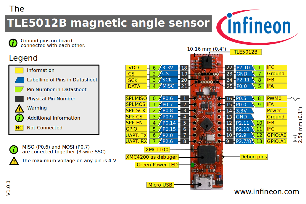 This pinout picture can be used for any TLE5012B Sens2Go kit (E1000,E5000,E9000) as well as for the breakout board of this PCBs.
The library examples have been built and successfully executed on the following hardware platforms:
| MCU Platforms |
|---|
| XMC1100 Boot Kit |
| XMC4700 Relax Kit for 5V Shields |
| Arduino Uno Rev3 |
| Cypress CYW943907AEVAL1F Evaluation Kit |
The Infineon TLE5012B Sens2Go evaluation kit use 3-wire SPI on board, so MISO/MOSI pin 0 and 1 are short. The Sensor PCB is breakable from the XMC2Go part. If you do so, than you can attache the Sensor PCB to any SPI interface but still only as a 3-wire SPI, so MISO/MOSI short.
The left over XMC2Go is still usable as and MSU for any other project but also has only a 3-wire SPI on board, otherwise it is identical to the XMC2Go so there is still a I2C, UART, PWM and GPIO available.
Use the 5V instead of the 3.3V connector for proper SPI connection due to the attached LED to the SCK pin.
The Infineon XMC4700 Relax Kit has up to five different SPI channels, whereas the default SPI is the one on the arduino header at its default position, SPI3 and SPI4 are already in use, so that at the end three SPIs can be used. On the XMC4700 Relax Kit the sensor can run with 3.3V or 5V (depending on the board version)
Also with this boards the 5V must be used for the sensor instead of the 3.3V. In case you eventually use 3.3V you get a very unstable communication. It may work sometimes but it can also loos its communication. If you use the full set of register functions, the amount of memory especially the amount of memory for global variables can very limiting.
To connect the 3-wire SSC interface to an Arduino with a 4-wire SPI interface you will need a resistor of 470 Ohm between the DATA line of the TLE5012B chip and combined MISO/MOSI pins of you MCU SPI interface (pin 11 on an UNO). If you are connecting multiple sensors they can all share one DATA line and one resistor. See the picture below of connect a bulk chip. The Sensor2Go evaluation board uses 3-wire SSC, so no resistor is needed between MISO and MOSI.
| TLE5012B Pin | Sensor2Go Pin | XMC 1100 Kit | Pin Function | Arduino Pin | Function |
|---|---|---|---|---|---|
| 2 | 3 / P0.8 | 13 / P0.7 | SCK | 13 | SCK |
| 3 | 4 / P0.9 | 10 / P0.9 | CSQ | 10 | SS |
| 4 | 2 / P0.7 | 12 / P1.1 | DATA R470 Ohm | 12 | MISO |
| no resistor | 11 / P1.0 | DATA R470 Ohm | 11 | MOSI | |
| 6 | 14 /3.3V | Vdd | Vdd | 3.3V or 5V | Power |
| 7 | 15 | GND | GND | GND | Ground |

The TLE5012B sensor comes in three different interface flavours for IIF, PWM or SPC/HSM interface. But all three have also the SSC interface included. This library yet only uses the SSC interface which gives you the access to all registers and functionalities of the sensor and its DSP. See in the TLE5012B manual for further information on the differences between the different interfaces. Internally the sensors where using fuses for setting the interface type and the default parameters used for the selected type. Using the register functions, these default setups can be changed and reprogrammed until the sensor is switched off or and firmwarereset is performed. This allows us to use the whole bandwidth of functions, even if we don't the right sensor type. The following table shows this settings:
| Type | E10000 | E3005 | E5000 | E5020 | E9000 |
|---|---|---|---|---|---|
| Interface | IIF (Incremental Interface) | HSM (all-Switch-Mode) | PWM (Pulse-Width-Modulation) | PWM (Pulse-Width-Modulation) | SPC (Short-PWM-Code) |
| SSC as push-pull output | SSC as push-pull output | SSC as push-pull output | SSC as push-pull output | SSC as push-pull output | |
| IFA/B/C as push-pull output | IFA/B/C as push-pull output | IFA as push-pull output | IFA as open-drain output | IFA as open-drain output | |
| Autocalibration | mode 1 | mode 1 | disabled | mode 2 | disabled |
| Prediction | disabled | enabled | enabled | disabled | disabled |
| Spike filter | disabled | disabled | enabled | enabled | enabled |
| Absolute count | enabled | ||||
| Hysteresis | 0.703° | 0.703° | disabled | disabled | disabled |
| Resolution | 12bit mode, 0.088° | PWM frequency is 244 Hz | PWM frequency is 1953 Hz | SPC unit time is 3 μs | |
| Update rate | 42.7 μs | 42.7 μs | 85.4 μs | 42.7 μs | 85.4 μs |
| Usage | BLDC motor commutation | replacement of three Hall | steering angle and actuator | steering angle and actuator | steering angle and actuator |
| switches for BLDC motor | position sensing | position sensing | position sensing | ||
| commutation |