Home
![]()
This Wiki tells some more in-depth technical information about the Dice Tower project. You can browse several subjects in the sidebar on the right.
The Dice Tower project is a project where my good friend / ex-colleague Nico Jongsma (aka Axios, not a Github user) came up with. He wanted to build a Dice Tower himself. To get an idea of what a Dice Tower could look like please Google the term: https://www.google.com/search?tbm=isch&q=dice+tower
Nico doesn't have the knowledge of the electronics and programming. The more I explained which parts and skills are needed, the simpler the electronic part of the project should be according to Nico. For me it was more like a challenge to get the elektronics working in such a way that totally fits in his cool looking Dice Tower.
Nico wanted to build a Dice Tower which have a kind of skull on the front of the tower. In that skulls there will be placed 2 red leds as eyes which should blink when a dice is put in the tower. Then he wanted a campfire somehere on the object. This will be simulated with 3 yellow leds (lights up as orange in my opinion). Then he wants to connect 4 miniature lanterns which should be permanantly lit. And finally he also wants to put 20 cold white leds in the tower which also should be lit permanently.
The things I added to the ideas of my colleague:
- A Wemos D1 mini to add interaction and animation effects to the Dice Tower. Later on in the project I added support for the MH-ET LIVE MiniKit ESP32 which has exactly the same pin layout as the Wemos D1 mini but has a ESP32 onboard instead of ESP8266 plus extra pins.
- A SW-18010P vibration sensor to detect the dice rolling through the tube of the Dice Tower.
- A configuration button.
- A configuration light (indicates whether a button press has been fetched or provide the status of things going on).
- A power-light to see whether the project gets powered correctly.
- A nice PCB design to flatten the space needed to drive all the leds. The original idea consisted of a main board with all connections to the leds soldered on it, then put a "interactive module" on top of that and at last a Wemos D1 mini or MH-ET LIVE ESP32 MiniKit on top of that. With a nice own designed PCB we got 1 layer less.
- Later on I added a "display module" which can be connected with a serial cable to the main PCB. To be able to use the display module the main boar dneeds to be driven by the MH-ET LIVE ESP32 MiniKit
More information about the functionality on the MH-ET LIVE ESP32 MiniKit can be found here: ESP32
More information about which pin is used for which functionality you can have a look at the Pinmapping scheme.
An overview of the menu on the ESP32 version can be found in the idea_for_menu.txt file in the repository.
If you plan to build your own Dice Tower you can find several website to let you inspire you how to build the Dice Tower. This Github repository only goes about the technical part of the Dice Tower. It assumes that you have some kind of a face or skull with eyes (2 red leds), a campfire (2 yellow / orange leds) and continous lit light (max. 24 leds).
You can build a device with prototype boards. We won't explain in detail how we build our prototype but you can find a short story and some photo's of our prototype based on the Wemos D1 mini here: Prototype PCB.
Another option is to use our own design PCB's (main board and display module. Information on our own PCB's can be fount at the page PCB and how to solder it can be found at the PCB soldering guide. Our PCB's are designed to use with a Wemos D1 mini, Wemos D1 mini pro or MH-ET LIVE ESP32 MiniKit. Any other device with exactly the same form factor and ESP8266 or ESP32 chip would probably work also.
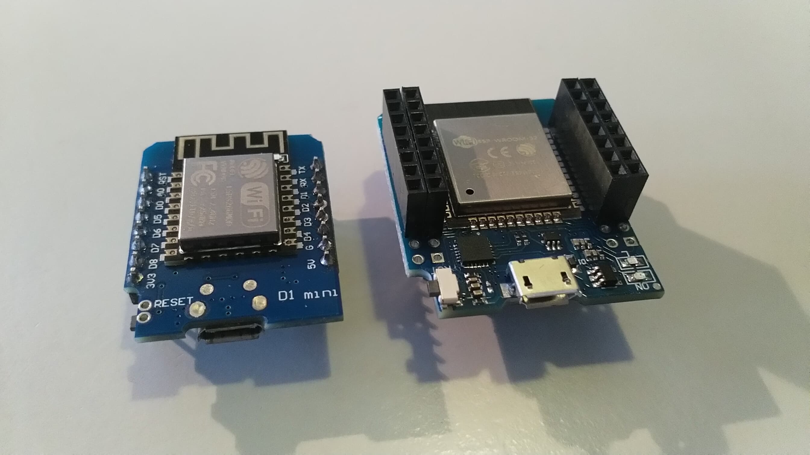
On the left you see the Wemos D1 mini and on the right the MH-ET LIVE MiniKit ESP32. The Wemos D1 mini pro is not displayed on this photo.
At last there is the software part. The software is compatible with the Wemos D1 mini, Wemos D1 mini and MH-ET LIVE ESP32 MiniKit and written for use on our designed PCB. If you can connect on of these development boards in the same way as we did our PCB then you can use any prottype board or breadboard for it. Information about the settings you can change can be found at the page Sketch settings. The software it self can be found in our repository.
Feel free to modify the software as long as you respect the GPL 3.0 license and the instructions in the sketch file it self.

This Wiki is licensed under a Creative Commons Attribution-ShareAlike 4.0 International License.