-
Notifications
You must be signed in to change notification settings - Fork 0
Prototype PCB

One of the methods to build the electrical part of your Dice Tower is by building a prototype PCB. You will need at least a 5 x 7 cm prototype board.
To create some flexibility in changing things later on it is advisable to also use a 4 x6 prototype PCB to create a detachable module. In that way you can use the 5 x 7 cm prototype board as a base plate where all wires to the leds and trigger gets connected to and the 4 x 6 cm prototype board as an upgradeable logic module.
Photo's of our prototype build of the Dice Tower can be found at the bottom of this page.
Below are the materials we used in our own Dice Tower project.
As said above we did use a 5 x 7 cm prototype PCB as base plate and a 4 x 6 prototype PCB as upgradeable logic module.
Theoretically any Arduino campatible development board can drive the project but since I have quite a few Wemos D1 mini's lying around I decided to go with that board. Currently the project doesn't use the WiFi capability of the Wemos D1 mini but the advantage of the choice to use this board is that WiFi functions can be added later on easily.
As long that you do not exceed the following limits you can use any led:
- Maxmimum 3.3V, 12 mA for the leds driven by the Wemos D1 mini (eyes, campfire and configuration/status led).
- Maxmimum 3.3V for the power led (not driven by GPIO but still the 3.3V power of the Wemos D1 mini).
- Maxmimum 5V for any other led.
As far as we found the data for it we do use the leds and resistors in the table below. We also specify to which power line it will be connected. You might need to recalculate resistor values if you use other leds with other characteristics.
| Amount | Color | Working voltage | Working current | Function | Power | Resistor |
|---|---|---|---|---|---|---|
| 2 | red (5 mm) | 1.9 - 2.1 V | 20 mA | Eyes | 3.3V | 100 Ω |
| 3 | yellow (5 mm) | 1.9 - 2.1 V | 20 mA | Campfire | 3.3V | 100 Ω |
| 1 | green (SMD 0603) | 3.0 - 3.2 V | 20 mA | Configuration / status led | 3.3V | 22 Ω (SMD 1206) |
| 20 | cold white (5 mm) | 3.0 - 3.2 V | 20 mA | Lights in the tower | 5V | 100 Ω |
| 4 | warm white (1) | 3.1 V (1) | 20 mA (1) | Lanterns around collection bin | 5V | 100 Ω |
| 1 | red (SMD 0603) | 1.8 - 2.0V | 20 mA | Continous power led | 3.3V | 100 Ω (SMD 1206) |
| 1 | - | - | - | Resistor for configuration button | 3.3V | 4.7 kΩ |
(1): The seller of the miniature lanterns did not specify the exact color, working voltage and working current. The seller only specified that it should operate on 3 to 5 volts. I assume it will be a warm white led with a working voltage of 3.1 and a working current of 20 mA.
On our self designed PCB we use other leds and resistors for the continous power led and the configuration led. Please see our PCB page.
We did use female heade pins on the base plate and placed in a U form. We did use the same form for the male header pins on the detachable module ends. |
Any button could do but we chose a sidewards 6 x 6 mm tactile button. Any depth of the button could do but we did use the default one of 5 mm.
The trigger provides a signal to the D3 pin of the Wemos D1 mini when a dice rolling through the tube of the Dice Tower has been detected. The trigger can be a anything that shorts the D3 pin of the Wemos D1 mini to ground. This could be for example 2 pieces of aluminium hitting each other when a dice rolls on it.
We have chosen for the SW-18010P vibration sensor of which DO connects to the D3 pin of the Wemos D1 mini, GND to GND on the Wemos D1 mini and VCC to 3V3 on the Wemos D1 mini.
When you use a button or any other electrical object that can short a circuit you can just use D3 and GND on the Wemos D1 mini. Polarity doesn't matter in that case.
You could decide to propogate the leds connections with pin headers so you can easily attach and detach led wires to it. Welding wires directly to the leds connections is something I would recommend to save some space in your enclosure.
To connect the leds from somewhere in the tower to your board you'll also needs wires. Wrapping wire will do. It is advisable to use black and red wires to easily distinguish the negative and positive sides coming from the leds.
This wires can also be used to create wire bridges between the pins of the Wemos D1 mini and the resistors for the interactive leds of the project. We also welded a lot soldertraces on the prototype PCB's.
To connect the vibration sensor to our prototype PCB we also did use Dupont cables female - female.
Ofcourse you also will need a micro-USB cable to power the board through the Wemos D1 mini.
Below are photo's of our prototype of the Dice Tower. Click on a picture to view the full size photo.
 |
|---|
| Total overview of prototype |
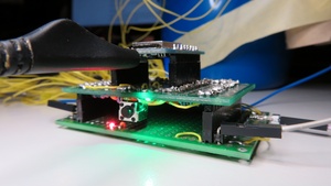 |
|---|
| Prototype stacked and powered |
 |
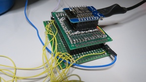 |
|---|---|
| Prototype stacked and not powered (1) | Prototype stacked and not powered (2) |
 |
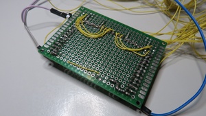 |
|---|---|
| Prototype base plate top | Prototype base plate bottom |
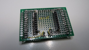 |
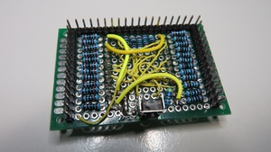 |
|---|---|
| Prototype logic module top | Prototype logic module bottom |
This Wiki is licensed under a Creative Commons Attribution-ShareAlike 4.0 International License.
