2022 Fall MCT Videoroom Documentation
Welcome to the Videoroom, one of two "portal" rooms in the MCT Department. The room is equipped with various audio-video systems for networked telepresence with a focus on musical collaboration. In this documentation we will seek to outline the setup and operation of the equipment in the Videorooom.
When using networked communication solutions, for musical collaboration or otherwise, effective visual telepresence is key. In musical contexts especially, the feeling of being in the same space is incredibly important to successful ensemble performance. Below is a list of the available video-related equipment in the Videoroom. In the sections that follow, we will look at how these systems can be configured and used for different tasks and applications.
Video equipment in the Videoroom consists predominantly of cameras for capturing the presence of those in the room, screens for monitoring the presence of the remote participants, a video matrix for choosing what the users see on the various screens and computers for running the various networking software. The specific equipment is listed below.
- Samsung DC55E TV
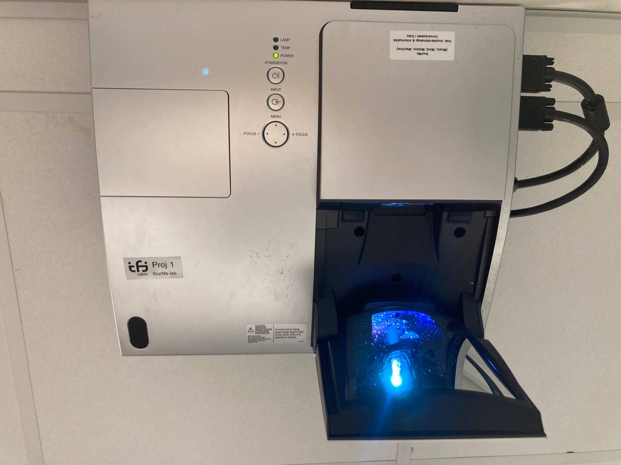
- Projector
- 2 Dell LCD Monitors
- 2 Samsung Monitors
- Logitech Carl Zeis HD
- Lumens PTZ (Currently inoperable)
- Zoom PC
- Mac Mini
- LOLA PC
- HDMI Matrix
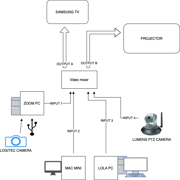
The above diagram illustrates the connections between the all equipment listed in the overview and approximately where they are located in the room.
Central to the video routing in the Videoroom is the HDMI matrix. The HDMI matrix takes as its inputs all of the various video sources from the three available computers and the Lumens PTZ camera. These are labelled numerically 1-4. The HDMI matrix also has two outputs labelled as Outputs A and B. Output A is connected to the Samsung TV and Output B is connected to the projector. Using the matrix, it is possible to independently route any of the input sources to either of the outputs.
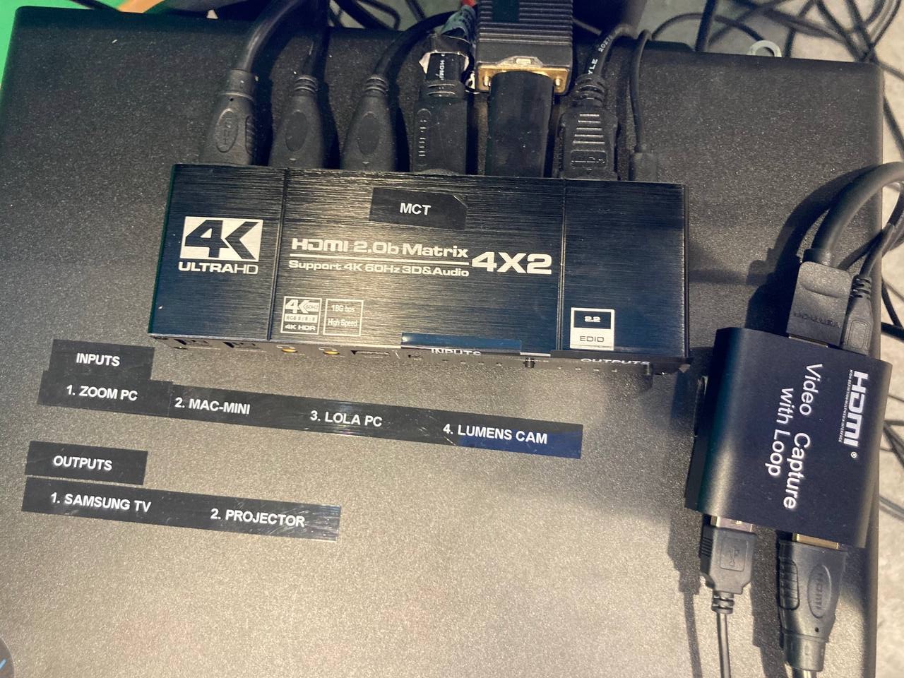
The inputs and outputs are labelled on the HDMI Matrix
The most convenient way to change what is seen on each screen is to use the HDMI matrix's remote:
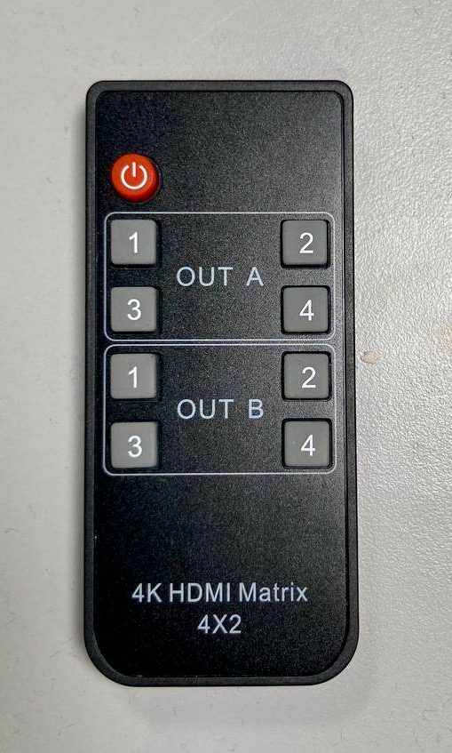
The remote is split into its two outputs. Using the buttons on the remote you can select which input the screen displays. Below is a breakdown of the routings possible using the remote.
- 1 - Zoom PC -> SAMSUNG TV 2 - MAC MINI -> SAMSUNG TV
- 3 - LOLA PC -> SAMSUNG TV 4 - LUMENS -> SAMSUNG TV
- 1 - Zoom PC -> PROJECTOR 2 - MAC MINI -> PROJECTOR
- 3 - LOLA PC -> PROJECTOR 4 - LUMENS -> PROJECTOR
Depending on which network solution you are using, you will be predominantly operating either the Zoom PC or the LOLA PC. Below is an illustrated step-by-step guide on booting and ensuring proper setup of the video sub-system.
- Turn on the Samsung TV using the remote:
If preferred, turn the projector on using the Power button:
Ensure that the appropriate PC is booted and logged in.
Zoom PC:

Mac mini and LOLA PC which their respective monitors:

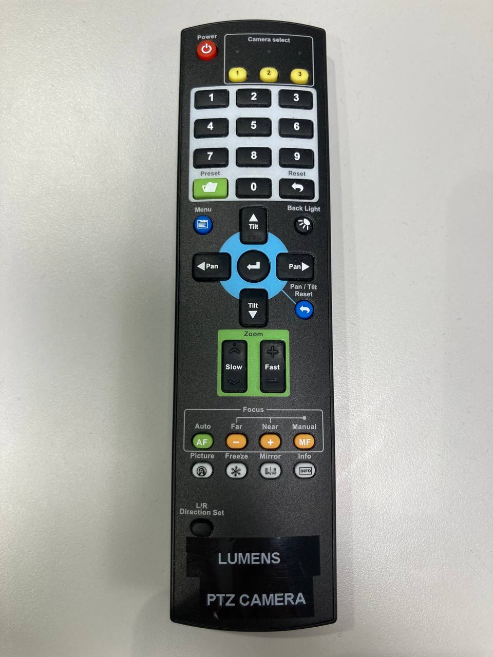
- Check the cameras are powered up and are connected.


The Logitech Camera is connect to the Zoom PC directly via USB. It can moved and controlled using the remote above.
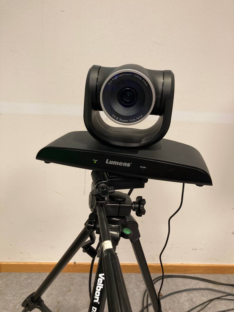
Lumens PTZ Camera is a high definition camera. Its HDMI output is sent to a video capture box which sends its signal both to the HDMI matrix (via HDMI) and to the Zoom PC (via USB). It can therefore be a camera for a Zoom call or a direct input source for either the Samsung TV or the projector.
-
Ensure all cables are connected to the HDMI matrix and that the HDMI matrix is switched on.
-
Using the HDMI matrix remote, change the video routing of the Samsung TV and projector to the appropriate input source. If, for instance, you wish to have the Zoom call on the Samsung TV, press button "1" in the Output A section of the remote. If you wish to have the video output from LOLA on the projector, press the "3" button in the Output B section of the remote.
-
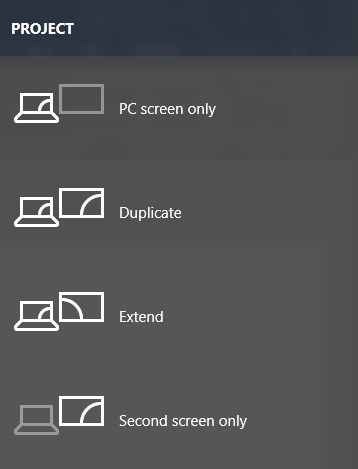
Finally you should also ensure that the display settings on the computer you are using are appropriate for you. On the PCs, using the shortcut Windows + P will bring up the display settings where you can choose if you wish to have "duplicated" (mirrored) screens or "extended".
Below is a table of troubleshooting options for the Videoroom video sub-system:
| Problem | Solutions |
|---|---|
| No picture on the Samsung TV | - Ensure the Samsung TV is connected to power and switched on -Ensure the proper routing with the HDMI matrix "Output A" section. If in doubt, begin by choosing input "1" for the Zoom PC - Using the "Source" button on the Samsung TV remote, try changing the source between HDMI 1 and 2. It is possible you will need to change the PC display settings. - On the PCs use the shortcut Windows + P to change the PCs display settings |
| No picture on the projector | - Ensure the projector is switched on - Change the input source using the "Output B" section of the HDMI matrix remote |
| Logitec Camera not working | -Ensure the camera is connected to power - Ensure the camera is connected via USB to the Zoom PC |
| Lumens PTZ Camera showing only coloured bars | Seek assistance from a member of the MCT staff |
This section describes the key elements of audio routing within, to, and from the Videoroom in the ZEB building at the Department of Musicology, University of Oslo (UIO). In addition to the main audio infrastructure considered herein, the Videoroom also contains various equipment and systems intended more for standalone or specialized use, but these will not be dealt with in any detail here. The scope of this guide is primarily the signal routing required for audio networking between the Videoroom and other locations at UIO, particularly the Portal also located in the ZEB building.
The following are the main equipment items relevant to audio routing and network signal transfer:
-
Analog Mixing Console; Mackie 32.8
-
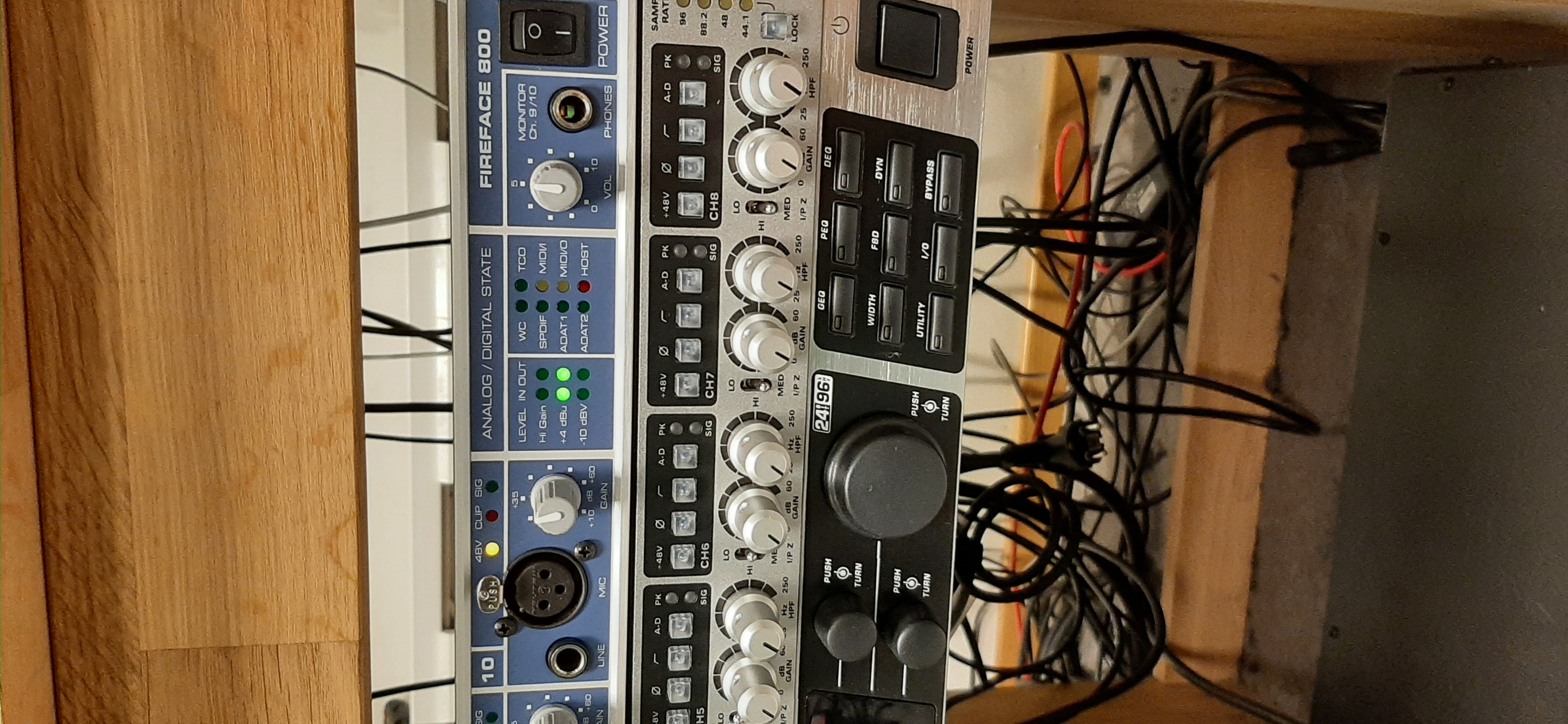
AD/DA Audio Interface; RME Fireface 800
-
Microphones
- 2 x Beyerdynamic MC530 condenser (floor standing L/R room mics)
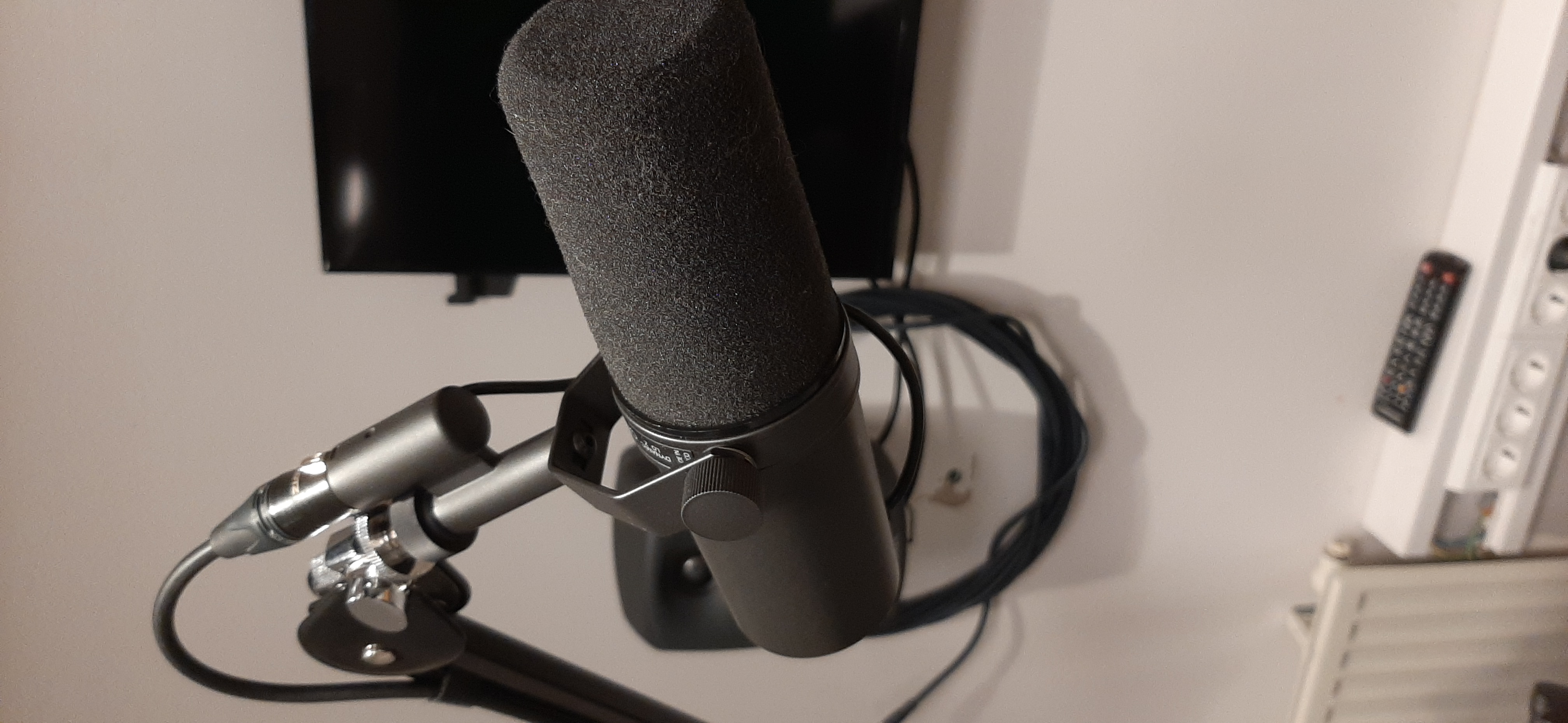
- 1 x Shure SM7B dynamic (mixing console talkback mic)
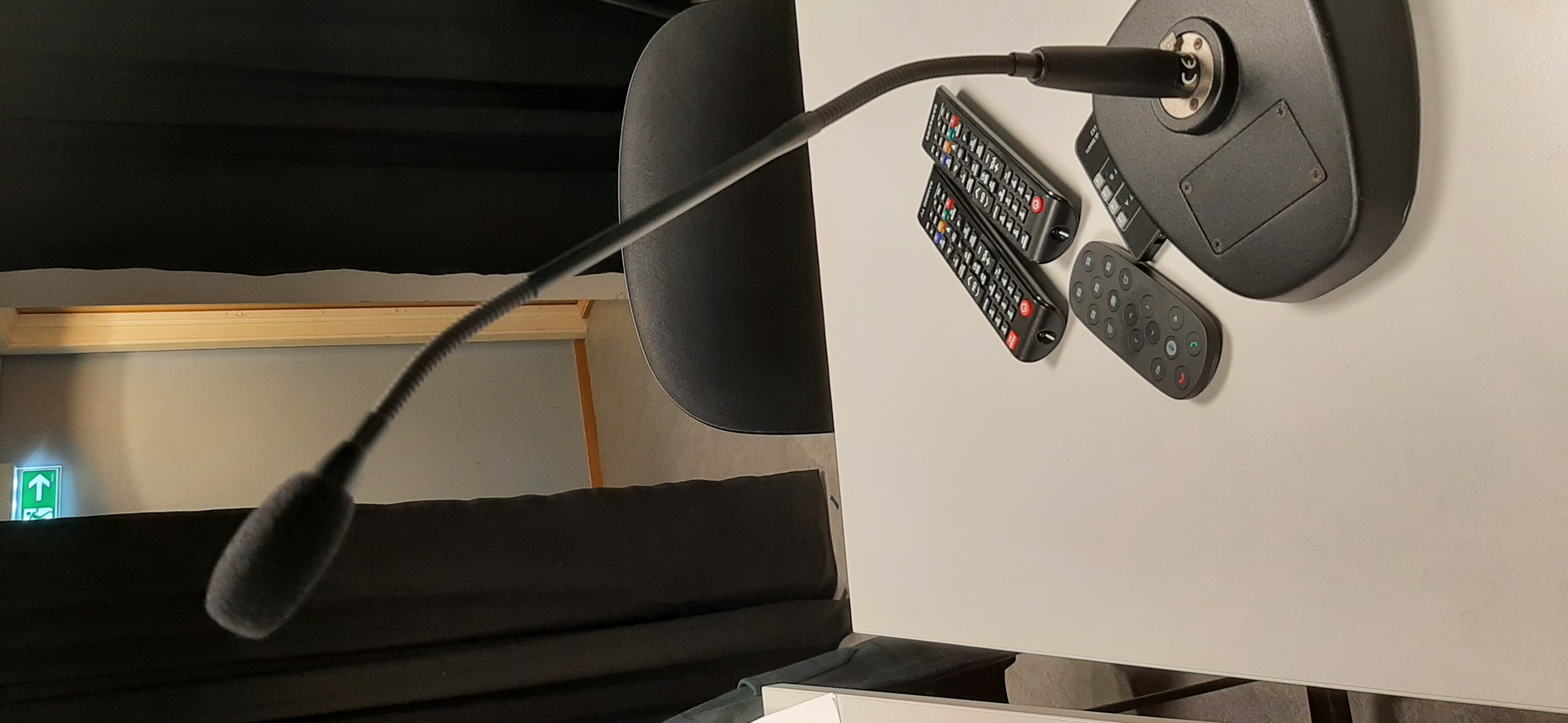
- 1 x Table top goose mic
-
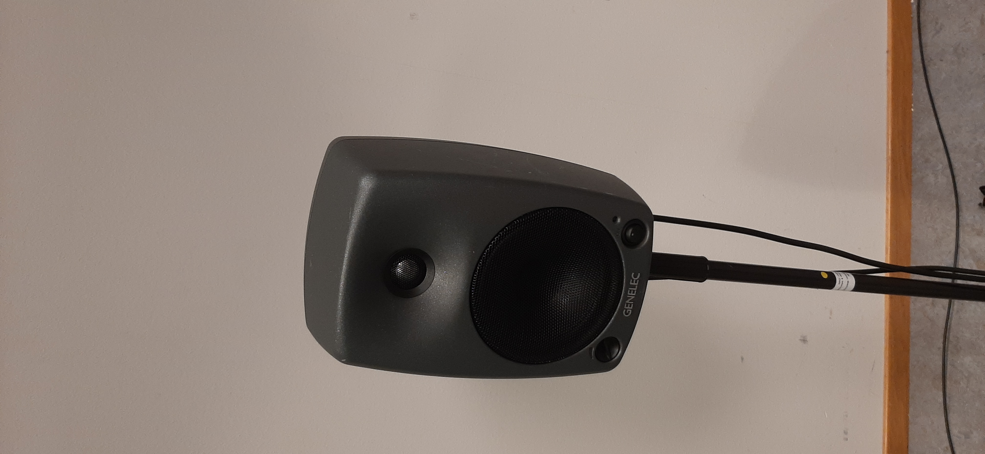
Studio monitors; Genelec 8030 (floor standing L/R speakers)
-
Zoom PC
-
Lola PC (with RME TotalMix software for digital routing and monitoring via the RME Fireface 800)
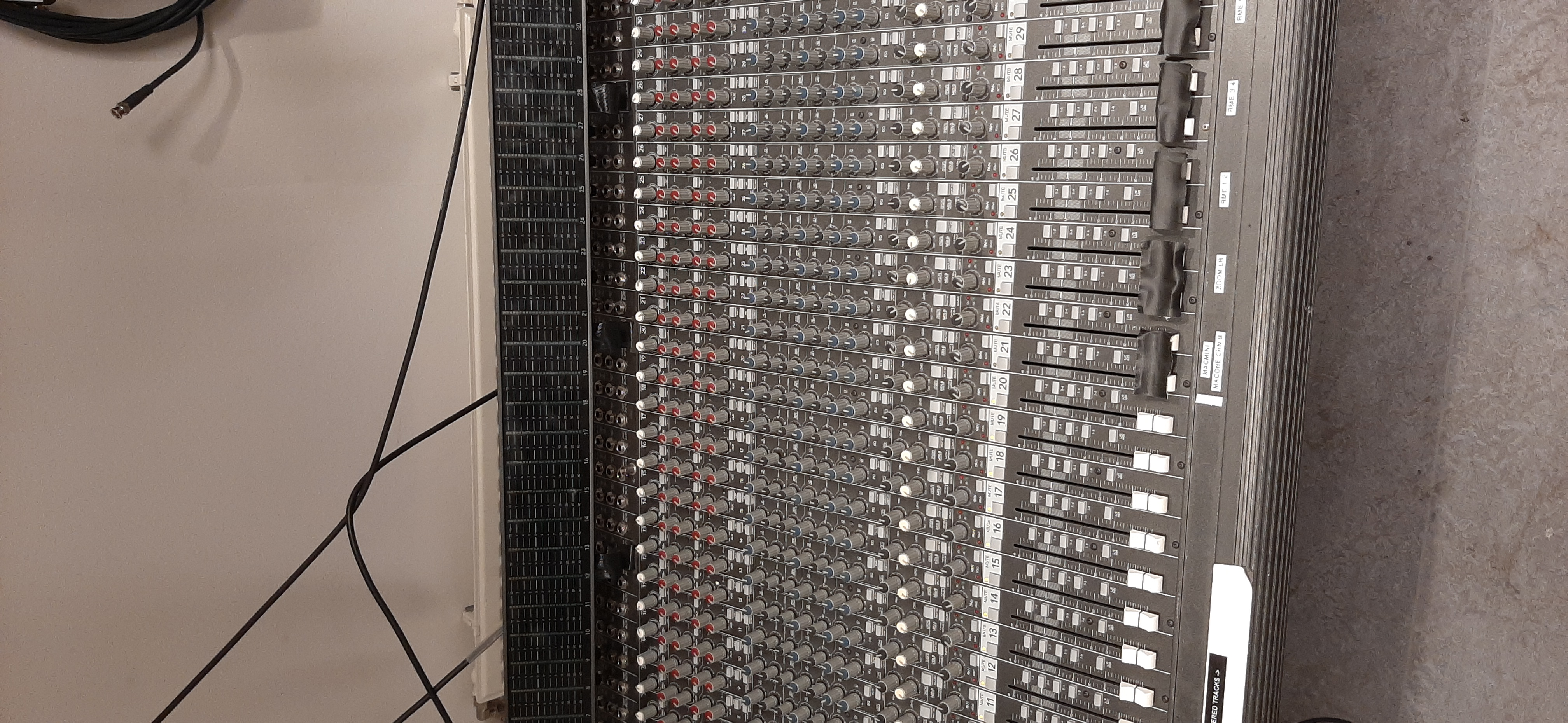
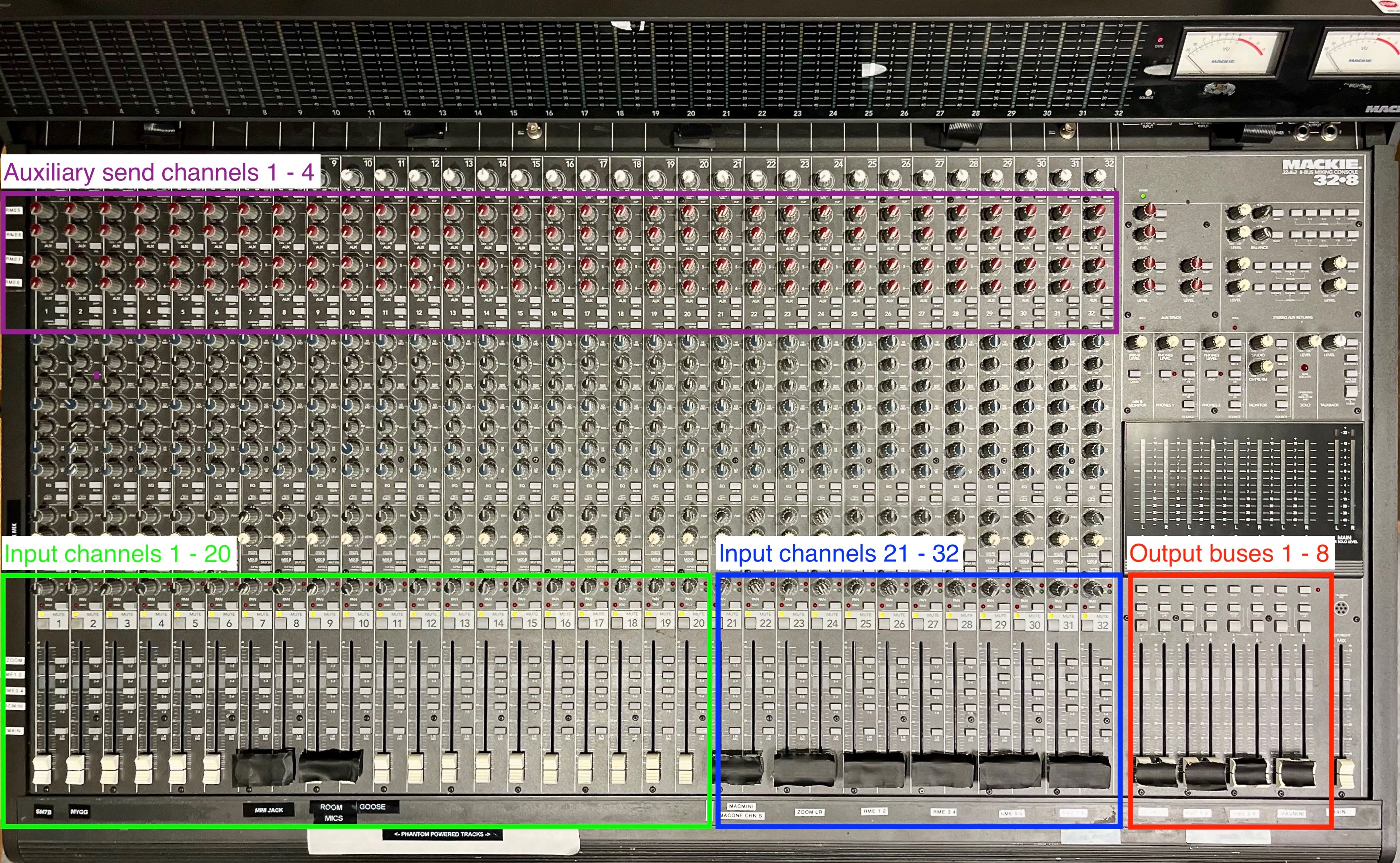
The mixer is the central hub for audio routing within, to, and from the Videoroom. It has 32 mic/line input channels with phantom power switchable on/off in groups of 8. Available outputs are via 2 stereo mix buses and 6 auxiliary send buses.
Input channels 1-20 are allocated to mic or line level signals. As per demarcation on the mixer the following connections represent the base configuration, whilst the remaining are free to use as desired for network performances and other applications:
- Ch 1: Shure SM7B dynamic (mixing console talkback mic)
- Ch 7-8: Mini jack (e.g. mp3 player, line level)
- Ch 9-10: Beyerdynamic MC530 (L/R room mics, phantom powered)
- Ch 11: Table top goose mic
Input channels 21-32 are allocated to line level stereo configured signals received from computers and the RME Fireface 800 interface in the Videoroom. As per demarcation on the mixer the following connections represent the base configuration:
- Ch 21-22: From Mac Mini headphone output
- Ch 23-24: From Zoom computer headphone output
- Ch 25-32: From RME outputs 1-8
Output buses 1-8 are allocated to sending line level stereo configured signals to computers and the RME Fireface 800 interface in the Videoroom. As per demarcation on the mixer the following connections represent the base configuration:
- Bus 1-2: To Zoom computer audio input
- Bus 3-4: To RME input 1-2
- Bus 5-6: To RME input 3-4
- Bus 7-8: To MAC Mini stereo audio input
The above listed bus connections are all made via the 'SUBMASTER/OUTPUTS' section at the rear panel of the mixer.
Additionally, auxiliary send outputs 1-4 are sent to RME inputs 5-8, respectively. These connections are made via the 'AUX SEND' output jacks behind the VU meters.
The Zoom computer in the Videoroom is connected to the Zoom computer in the Portal via a conventional computer network for sending and receiving audio and video between the rooms.
The configuration for sending and receiving audio over Zoom has been limited to one stereo signal. Demarcation stickers on the mixer illustrate the signal flow.
- Make sure you are connected to the Zoom room
- Press the small arrow icon next to the microphone in the lower left corner of the screen to open up a list with available audio inputs
- Select Synapsis HD as both audio in and out
Input signals from Channels 1-20 are enabled for sending via Zoom by pressing the respective channel assignment button marked '1-2' (aligned with the 'ZOOM' label on the left side of the mixer). Turning up Bus 1-2 fader on the right side of the mixer (also labeled 'ZOOM') will send audio to the Zoom computer.
Aural monitoring of inputs or outputs can be done by pressing respective channel assignment button 'L/R MIX', but care must be taken not to create feedback via the speakers and microphones in the room.
Audio sent from the Zoom computer in the Portal is received via mixer input channels 23-24. To monitor audio received via Zoom press the channel assignment buttons marked 'L/R Mix' and turn up the channel faders (labeled 'ZOOM LR).
In addition to the general precautions given regarding feedback above, additional care must be taken when sending and receiving audio via Zoom simultaneously to ensure that mixer channels 23-24 assignment buttons '1-2' are NOT pressed.
The LoLa computer in the Videoroom is connected to the LoLa computer in the Portal (or other remote LoLa computer) via an ultra-low latency network for sending and receiving audio and video between the rooms.
The characteristics of the LoLa network make it possible to transmit more audio channels than via Zoom, and still maintain an acceptable audio quality and synchronization.
A total of 8 channels have been configured for transmitting audio over LoLa between the Videoroom and the Portal. In the Videoroom the RME Fireface 800 interface handles the AD/DA conversion between the mixer and the LoLa computer. The RME and LoLa computer are connected via FireWire 400.
- Before opening LoLa, make sure the RME interface is turned on
- LoLa will give you a warning if the interface is not turned on
- After opening LoLa go into the LoLa setup and make sure that ASIO Fireface is selected as the ASIO device
- Make sure that the sample rate is set to 48000 on both sides. LoLa will not work otherwise
- Lastly select the number of inputs you will be using. The standard amount is 4, but the interface has up to 10 analog inputs
Input signals from Channels 1 - 20 are enabled for sending via LoLa over RME inputs 1/2 and 3/4 by pressing the respective channel assignment button marked '3-4' and '5-6'. The remaining 4 channels can be sent via LoLa over RME inputs 5-8 utilizing auxiliary sends 1-4 on the mixer as described above.
Audio sent from the LoLa computer in the Portal is received by mixer input channels 25 - 32 via RME outputs 1-8. To monitor audio received via LoLa press the respective channel assignment buttons marked 'L/R Mix' and turn up the channel faders (labeled 'RME 1 2' through 'RME 7 8').
In addition to the general precautions given regarding feedback above, additional care must be taken when sending and receiving audio via LoLa simultaneously to ensure that mixer channels 25-32 assignment buttons '3-4' or '5-6' are NOT pressed.
As mentioned earlier the mixer should not be shut down at all, instead you should follow these instructions to reset the mixer to a blank slate:
- Turn off all monitors used
- Turn off the RME interface
- Turn off computer(s). If you've been using the Mac Mini then make sure to log out and turn the volume down and flip the mute switch on the McOne
- Mixer
- Turn down all faders
- Turn all auxiliary send dial controls to zero
- Disengage all channel assignment buttons
- Mute all input channels
If you're having any trouble with either sending or receiving audio please make sure that:
- Mixer is powered on
- Monitors are on and the volume is not turned down (front knob on the left side of the monitor)
- Everything is plugged into the mixer
- If you're using a microphone which requires phantom power, make sure it's activated
- The trim pot on the channel is set at an appropriate level
- The volume fader is set at an appropriate level
- The mute button is not activated
- If you are having trouble sending audio, make sure you are sending the signal to the correct submix
- The 5 buttons on the left-hand side of the mixer shows you where to send the signal
- Try sending audio to the main speakers, if you're hearing nothing then check the points above

