Skip to content
New issue

Have a question about this project? Sign up for a free GitHub account to open an issue and contact its maintainers and the community.

By clicking “Sign up for GitHub”, you agree to our terms of service and privacy statement. We’ll occasionally send you account related emails.

Already on GitHub? Sign in to your account

basic config: add actuators page (replacing motors) #1704

Merged
merged 6 commits into from
Jan 12, 2022
Merged
Show file tree
Hide file tree
Changes from all commits
Commits
File filter

Filter by extension

Filter by extension

Conversations
Failed to load comments.
Jump to
Jump to file
Failed to load files.
Diff view
Diff view
Sorry, something went wrong. Reload?
Sorry, we cannot display this file.
Sorry, this file is invalid so it cannot be displayed.
Binary file added assets/config/actuators/qgc_actuators_mc_aux.png
Sorry, something went wrong. Reload?
Sorry, we cannot display this file.
Sorry, this file is invalid so it cannot be displayed.
Sorry, something went wrong. Reload?
Sorry, we cannot display this file.
Sorry, this file is invalid so it cannot be displayed.
Sorry, something went wrong. Reload?
Sorry, we cannot display this file.
Sorry, this file is invalid so it cannot be displayed.
Binary file added assets/config/actuators/tilt_axis.png
Sorry, something went wrong. Reload?
Sorry, we cannot display this file.
Sorry, this file is invalid so it cannot be displayed.
69 changes: 69 additions & 0 deletions assets/config/actuators/tilt_axis.tex
Original file line number Diff line number Diff line change
@@ -0,0 +1,69 @@
% latexmk -pdf tilt_axis.tex
% pdftoppm tilt_axis.pdf tilt_axis.png -png
\documentclass[border=3pt,tikz]{standalone}
\usepackage{physics}
\usepackage{tikz}
\usepackage{tikz-3dplot}
\usepackage[outline]{contour} % glow around text
\usepackage{xcolor}

\colorlet{veccol}{green!50!black}
\colorlet{projcol}{blue!70!black}
\colorlet{myblue}{blue!70!black}
\colorlet{mydarkblue}{blue!50!black}
\tikzset{>=latex} % for LaTeX arrow head
\tikzstyle{proj}=[projcol!80,line width=0.08] %very thin
\tikzstyle{area}=[draw=veccol,fill=veccol!80,fill opacity=0.6]
\tikzstyle{vector}=[->,veccol,thick]
\tikzstyle{darkvector}=[->,veccol!70!black,thick]
\usetikzlibrary{angles,quotes} % for pic (angle labels)
\contourlength{1.3pt}

\begin{document}


\tdplotsetmaincoords{60}{110}
\begin{tikzpicture}[scale=2,tdplot_main_coords]

% VARIABLES
\def\rvec{1}
\def\thetavec{-20}
\def\thetavecmax{-70}
\def\phivec{-60}

% AXES
\coordinate (O) at (0,0,0);
\draw[thick,->] (0,0,0) -- (-2.5,0,0) node[anchor=north west]{$x$};
\draw[thick,->] (0,0,0) -- (0,1.7,0) node[anchor=north west]{$y$};
\draw[thick,->] (0,0,0) -- (0,0,1.7) node[anchor=south]{$-z$};

% VECTORS
\tdplotsetcoord{P}{\rvec}{\thetavec}{\phivec}
\draw[-stealth,red] (O) -- (P) node[above right=-2] {$P_{0}$};
\draw[dashed,red] (O) -- (Pxy);
\draw[dashed,red] (P) -- (Pxy);

\tdplotsetcoord{P}{\rvec}{\thetavecmax}{\phivec}
\draw[-stealth,blue] (O) -- (P) node[above right=-2] {$P_{1}$};
\draw[dashed,blue] (O) -- (Pxy);
\draw[dashed,blue] (P) -- (Pxy);

% ARCS
\tdplotdrawarc[->]{(O)}{-0.6}{0}{\phivec}
{anchor=south}{$\alpha$}
\tdplotsetthetaplanecoords{\phivec}
\tdplotdrawarc[->,tdplot_rotated_coords,red]{(0,0,0)}{0.7}{0}{\thetavec}
{anchor=south west}{\hspace{-2mm}$\theta_0$}

\tdplotdrawarc[->,tdplot_rotated_coords,blue]{(0,0,0)}{0.3}{0}{\thetavecmax}
{anchor=south west}{\hspace{-3.5mm}$\theta_1$}

\node[draw=none] at (1,1) {\begin{tabular}{l}
$\alpha$: tilt direction\\
$\theta_{0}$: minimum tilt angle \\
$\theta_{1}$: maximum tilt angle
\end{tabular}};

\end{tikzpicture}

\end{document}
3 changes: 2 additions & 1 deletion en/SUMMARY.md
Original file line number Diff line number Diff line change
Expand Up @@ -41,7 +41,8 @@
* [Flight Modes](config/flight_mode.md)
* [Battery](config/battery.md)
* [Safety](config/safety.md)
* [Motors/Servos](config/motors.md)
* [Motors](config/motors.md)
hamishwillee marked this conversation as resolved.
Show resolved Hide resolved
* [Actuators](config/actuators.md)
* [Autotune](config/autotune.md)
* [Airframe Builds](airframes/README.md)
* [Airframes Reference](airframes/airframe_reference.md)
Expand Down
1 change: 1 addition & 0 deletions en/config/README.md
Original file line number Diff line number Diff line change
Expand Up @@ -25,6 +25,7 @@ The sub topics cover each of the steps in detail (first install the PX4 firmware
* [Battery](../config/battery.md) (optional)
* [Safety](../config/safety.md) (optional)
* [Motors/Servos](../config/motors.md)
* [Actuators](../config/actuators.md)
* [Autotune](../config/autotune.md)


Expand Down
150 changes: 150 additions & 0 deletions en/config/actuators.md
Original file line number Diff line number Diff line change
@@ -0,0 +1,150 @@
# Actuator Configuration and Testing

:::note
hamishwillee marked this conversation as resolved.
Show resolved Hide resolved
The *Actuators* view is only displayed if dynamic control allocation is enabled using the [SYS_CTRL_ALLOC](../advanced_config/parameter_reference.md#SYS_CTRL_ALLOC) parameter.
This replaces geometry and mixer configuration files with configuration using parameters.
You should also ensure that the appropriate airframe type is selected using [CA_AIRFRAME](../advanced_config/parameter_reference.md#CA_AIRFRAME).

The easiest way to try this out in simulation is to use the following make target, which has control allocation pre-enabled:
```
make px4_sitl gazebo_iris_ctrlalloc
```
:::

After selecting an [airframe](../config/airframe.md) you will generally need to configure the specific geometry, assign actuators to outputs, and test the actuator response.
This can be done in *QGroundControl*, under the **Vehicle Setup > Actuators** tab.

The multicopter configuration screen looks like this.

![Actuators MC (QGC)](../../assets/config/actuators/qgc_actuators_mc_aux.png)

Note that some settings are hidden unless you select the **Advanced** checkbox in the top right corner.

## Geometry

The geometry section is used to configure any additional geometry-related settings for the selected [airframe](../config/airframe.md).
hamishwillee marked this conversation as resolved.
Show resolved Hide resolved
The UI displays a customised view for the selected type; if there are no configurable options this may display a static image of the frame geometry, or nothing at all.

The screenshot below shows the geometry screen for a multicopter frame, which allows you to select the number of motors, their relative positions on the frame, and their expected spin directions (select "**Direction CCW**" for counter-clockwise motors).
This particular frame also includes an image showing the motor positions, which dynamically updates as the motors settings are changed.

![Geometry MC (QGC)](../../assets/config/actuators/qgc_actuators_mc_geometry.png)

A fixed wing airframe would instead display the parameters that define control surfaces, while a VTOL airframe could display both motors and control surfaces.


### Conventions

The following sections contain the conventions and explanations for configuring the geometry.

#### Coordinate system

The coordinate system is NED (in body frame), where the X axis points forward, the Y axis to the right and the Z axis down.
Positions are relative to the center of gravity (in meters).

#### Control Surfaces and Servo Direction

Control surfaces use the following deflection direction convention:
- horizontal (e.g. Aileron): up = positive deflection
- vertical (e.g. Rudder): right = positive deflection
- mixed (e.g. V-Tail): up = positive deflection

![Plane Deflections](../../assets/config/actuators/plane_servo_convention.png)

:::note
If a servo does not move in the expected direction set in the geometry, you can reverse it using a checkbox on the Actuator Output.
:::


### Motor Tilt Servos

Tilt servos are configured as follows:
- The reference direction is upwards (negative Z direction).
- Tilt direction: **Towards Front** means the servo tilts towards positive X direction, whereas **Towards Right** means towards positive Y direction.
- Minimum and maximum tilt angles: specify the physical limits in degrees of the tilt at minimum control and maximum respectively.
An angle of 0° means to point upwards, then increases towards the tilt direction.
:::note
Negative angles are possible. For example tiltable multirotors have symmetrical limits and one could specify -30 as minimum and 30 degrees as maximum.
:::
:::note
If a motor/tilt points downwards and tilts towards the back it is logically equivalent to a motor pointing upwards and tilting towards the front.
:::
- Control: depending on the airframe, tilt servos can be used to control torque on one or more axis (it's possible to only use a subset of the available tilts for a certain torque control):
- Yaw: the tilts are used to control yaw (generally desired).
If four or more motors are used, the motors can be used instead.
- Pitch: typically differential motor thrust is used to control pitch, but some airframes require pitch to be controlled by the tilt servos.
Bicopters are among those.
- Tiltable motors are then assigned to one of the tilt servos.

![Tilt Axis](../../assets/config/actuators/tilt_axis.png)


### Bidirectional Motors
Copy link
Collaborator

Choose a reason for hiding this comment

The reason will be displayed to describe this comment to others. Learn more.

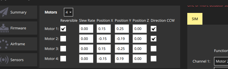
@bkueng Note, I have updated this section from reversible to bidirectional motors. Why? Because we were also using reversible to mean a motor that can configure to go in either direction (but not switch while in use)

Do you think perhaps we could also change QGC to use the term "bidirectional"?

Copy link
Collaborator

Choose a reason for hiding this comment

The reason will be displayed to describe this comment to others. Learn more.

@bkueng Did you see this? Are you otherwise good for this to merge?

Copy link
Member Author

Choose a reason for hiding this comment

The reason will be displayed to describe this comment to others. Learn more.

Yes bidirectional is fine.

  • instead of 'required', can you use something like 'you have the option to...'? Even for rovers you don't need it, if you don't care about only going forwards.
  • the option will only be displayed if relevant for the frame type -> you always have the option under 'advanced'

Copy link
Collaborator

Choose a reason for hiding this comment

The reason will be displayed to describe this comment to others. Learn more.

Yes bidirectional is fine.

It would be even better if you changed it in QGC :-).

I've added as (accepted) suggestions below. Note that when I pressed advanced checkbox in Sim last time I did not see the reversible option, which is why I assumed this is a feature of the airframe. Nevertheless I'll assume the sim is incorrect, not the intent.

Copy link
Member Author

Choose a reason for hiding this comment

The reason will be displayed to describe this comment to others. Learn more.

Already in the pipeline: PX4/PX4-Autopilot@d23b5fd :-)
Hmm did you check on the geometry side?

image

Copy link
Collaborator

Choose a reason for hiding this comment

The reason will be displayed to describe this comment to others. Learn more.

This is simulated iris from 23 December, with advanced checked.

image

Copy link
Collaborator

Choose a reason for hiding this comment

The reason will be displayed to describe this comment to others. Learn more.

Fixed in todays build:
image
So we can forget this


Some vehicles may use bidirectional motors (i.e. motor spins in direction 1 for lower output range and in direction 2 for the upper half).
For example, ground vehicles that want to move forwards and backwards, or VTOL vehicles that have pusher motors that go in either direction.

If bidiectional motors are used, make sure to select the **Reversible** checkbox for those motors (the checkbox is displayed as an "advanced" option).

![Reversible](../../assets/config/actuators/qgc_geometry_reversible.png)

Note that you will need to also ensure that the ESC associated with bidirectional motors is configured appropriately (e.g. 3D mode enabled for DShot ESCs, which can be achieved via [DShot commands](../peripherals/dshot.md#commands)).


## Actuator Outputs

The actuators and any other output function can be assigned to any of the physical outputs.
Each output has its own tab, e.g. the PWM MAIN or AUX output pins, or UAVCAN.

PWM outputs are grouped according to the hardware groups of the autopilot.
Each group allows to configure the PWM rate or DShot/Oneshot (if supported).

:::note
For boards with MAIN and AUX, prefer the AUX pins over the MAIN pins for motors, as they have lower latency.
:::

The AUX pins have additional configuration options for camera capture/triggering.
Selecting these requires a reboot before they are applied.

hamishwillee marked this conversation as resolved.
Show resolved Hide resolved

## Actuator Testing

<!-- Not documented: "Identify and assign motors" -->

When testing actuators, make sure that:
- Motors spin at the "minimum thrust" position.

The sliders snap into place at the lower end, and motors are turned off (disarmed).
The "minimum thrust" position is the next slider position, which commands the minimum thrust.
For PWM motors, adjust the minimum output value such that the motors spin at that slider position (not required for DShot).
:::note
VTOLs will automatically turn off motors pointing upwards during fixed-wing flight.
For Standard VTOLs these are the motors defined as multicopter motors.
For Tiltrotors these are the motors that have no associated tilt servo.
Tailsitters use all motors in fixed-wing flight.
:::
- Servos move into the direction of the convention described above.
:::note
A trim value can be configured for control surfaces, which is also applied to the test slider.
:::

Note the following behaviour:
Copy link
Collaborator

Choose a reason for hiding this comment

The reason will be displayed to describe this comment to others. Learn more.

Should we perhaps have at least some of this stuff first as safety warnings before the guidance? e.g. kill switch, safety button, and perhaps removing props?

Copy link
Member Author

Choose a reason for hiding this comment

The reason will be displayed to describe this comment to others. Learn more.

Yes we could. Although the switch in the UI already says it.

- If a safety button is used, it must be pressed before actuator testing is allowed.
- The kill-switch can still be used to stop motors immediately.
- Servos do not actually move until the corresponding slider is changed.
- The parameter [COM_MOT_TEST_EN](../advanced_config/parameter_reference.md#COM_MOT_TEST_EN) can be used to completely disable actuator testing.
- On the shell, [actuator_test](../modules/modules_command.md#actuator-test) can be used as well.

### Reversing Motors

The motors must turn in the direction defined in configured geometry ("**Direction CCW**" checkboxes).
If any motors do not turn in the correct direction they must be reversed.

There are several options:
- If the ESCs are configured as [DShot](../peripherals/dshot.md) you can reverse the direction via UI (**Set Spin Direction** buttons).
Note that the current direction cannot be queried, so you might have to try both options.
- Swap 2 of the 3 motor cables (it does not matter which ones).

:::note
If motors are not connected via bullet-connectors, re-soldering is required (this is a reason, among others, to prefer DShot ESCs).
:::
4 changes: 4 additions & 0 deletions en/config/motors.md
Original file line number Diff line number Diff line change
@@ -1,5 +1,9 @@
# Motor/Servo Checks

:::note
This section is being replaced by an [Actuators](../config/actuators.md) configuration screen.
:::

After the airframe is setup and configured you should validate the motor assignment and spin direction, and the servo response.
This can be done in *QGroundControl*, under the [Vehicle Setup > Motors](https://docs.qgroundcontrol.com/en/SetupView/Motors.html) tab.

Expand Down