Hardware Configuration
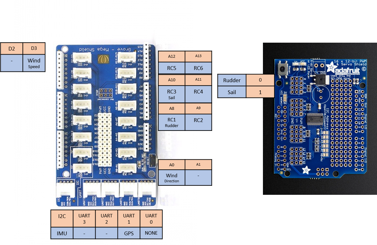
Here is a diagram defining the boards connectors name and their equivalent on the Arduino :
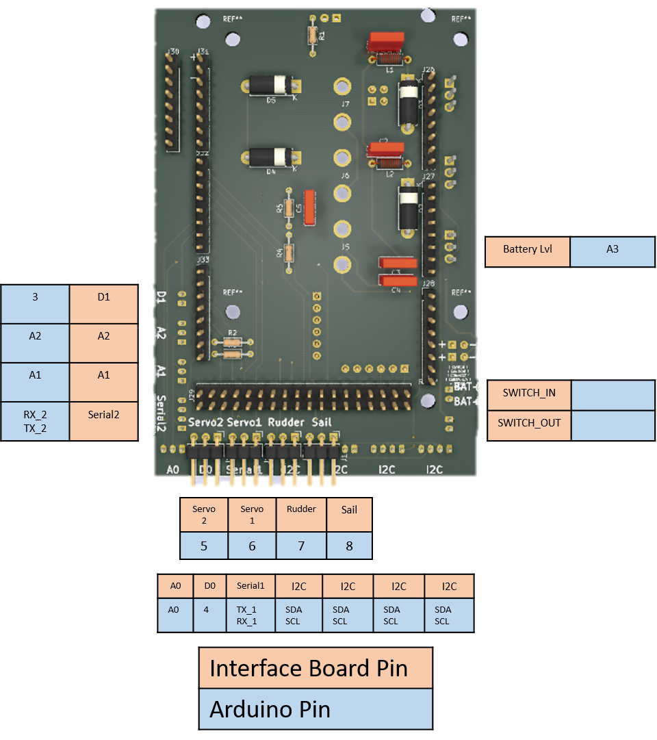
Here is a diagram defining the boards connectors name and their equivalent with the sensors and motors :
We will change two files to configure the sailboat hardware. This concerns matching the pins number to the sensors, matching the address of the different I2C modules and enter the different parameters for the controls (rudder and sail : min and max angles).
Normally, you would have attached the Sail actuator to the "Sail" connector, the Rudder actuator to the "Rudder" connector, etc...
If not, the configuration can be changed to match your hardware configuration.
Each sensors might have different minimum and maximums. For instance, our wind sensor gives us a reading of 0.23V when the wind sensor is at 0 degrees, and 4.83V when at 359 degrees. We have to put those parameters to have the right readings of the sensor.
The parameters can be found by testing the sensor with the Arduino in an independent sketch (project) to see what it reads.
Two configuration file exist. One for boat parameters and one common for pin numbers. We will first look at the boat parameters file config-<SailboatName>.h and then the common pin numbers config config-Sailboat.h. The latter is also used as the main configuration file, as such you have to link the parameter file config-<SailboatName>.h inside config-Sailboat.h. This will be explained later.
For the first config file, you will have to create a new file for your own boat. But let us see an example file such as ours AutonomousSailboat/libraries/Sailboat/config-SailboatPRO.h.
The second file is common to all sailboat configurations : AutonomousSailboat/libraries/Sailboat/config-Sailboat.h.
Let's focus on the configuration part of config-SailboatPRO.h. You can copy this file to make your own.
/**********************************************HARDWARE********************************************/
//RC Transceiver
#define HK_TR6

//Using Grove Shield or not
#define SERVO_SHIELD

//IMU
//#define CMPS12_IMU
#define XSENS_IMU
//#define USE_ARDUINO_GPS
//#define USE_ARDUINO_WIND
#define FUSE_GPS_IMU


//WIND
#define WIND_ANEMOMETER_PIN 3
First we must choose the features we want on our boat. #define HK_TR6 defines a RC receiver that we use the boat. Implemented RC receiver are found in config-RC.h.
Then we define whether we use the Servo Shield or not with #define SERVO_SHIELD. This defines whether you have the custom board or the off-the-shelf control box. Comment this line if you have a custom board.
Then we define which IMU we use. At the moment only XSens and CMPS12 are implemented. Add your define here for your new IMU.
Then we define whether GPS and Wind sensors are attached to the Arduino or the Raspberry Pi. Comment if they are on the Raspberry Pi or add them if they are on the Arduino.
Finally we have an optional feature which fuses data between GPS and IMU to have better data on the velocity of the boat. Comment it if you don't want that feature.
In the end, an optional anemometer is put with it's pin #define WIND_ANEMOMETER_PIN 3. If you don't have an anemometer comment it.
We have then the configurations for the servo motors and the wind sensor.
/*****************************************CONFIGURATION****************************************/
/**CONFIG**/
/**********/
//WIND
#define WIND_SENSOR_MIN 48
#define WIND_SENSOR_MAX 990

//RUDDER
#define RUDDER_POS_MIN  68
#define RUDDER_POS_NEUTRAL  103
#define RUDDER_POS_MAX  150

#define RUDDER_MIN  -38
#define RUDDER_NEUTRAL  0
#define RUDDER_MAX  45

//SAIL
#define SAIL_MIN 0
#define SAIL_NEUTRAL SAIL_MIN
#define SAIL_MAX 90

#define WINCH_ANGLE_MIN 38
#define WINCH_ANGLE_NEUTRAL WINCH_ANGLE_MIN
#define WINCH_ANGLE_MAX 112
#define WINCH_DIAMETER 23 // in mm
First we have the wind sensor values to configure :
//WIND
#define WIND_SENSOR_MIN 48
#define WIND_SENSOR_MAX 990
The values can be found by using the function analogRead(int pin) in the Arduino. This gives a value 0-1024 which corresponds to the voltage 0-5V. Try to find the minimum and maximum value of your wind sensor and enter them in the configuration file.
Next is the Rudder position.
//RUDDER
#define RUDDER_POS_MIN  68
#define RUDDER_POS_NEUTRAL  103
#define RUDDER_POS_MAX  150

#define RUDDER_MIN  -38
#define RUDDER_NEUTRAL  0
#define RUDDER_MAX  45
The defined variable RUDDER_POS_* is the value given to the servomotor for the minimum and maximum angle. This uses the function servo.write(int angle) which comes from the library #include <Servo.h>, a standard library in the Arduino. The value generally represent the angle (in degrees) of the servo motor. As such a value servo.write(90) should put the servo-motor at 90 degrees. This is not always the case and depending on the reference frame of the servo-motor in the boat, this can change. In this case, you have to enter the different minimum and maximum angles of the servo-motor that is used for the rudder.
The defined varialbe RUDDER_* are the real angles of the Rudder. Those are not the values of the servo-motor but the Rudder. This is used to interpolate the values from the servo-motor to the real rudder angle. In our case, the rudder was not able to go full -45,45 degrees, so we changed that accordingly.
Next is the Sail parameters.
//SAIL
#define SAIL_MIN 0
#define SAIL_NEUTRAL SAIL_MIN
#define SAIL_MAX 90

#define WINCH_ANGLE_MIN 38
#define WINCH_ANGLE_NEUTRAL WINCH_ANGLE_MIN
#define WINCH_ANGLE_MAX 112
#define WINCH_DIAMETER 23 // in mm
The defined variable SAIL_* are the same as RUDDER_*. They represent the absolute angles of the Sail on your boat.
The defined variable WINCH_ANGLE_* represent the minimum and maximum angle on the servo-motor that is used as a wind for the sail. The same way as the Rudder, these values are the ones used with servo.write(int angle) and represent the angle in degrees at which when the winch is at minimum, the sail is at 0 and when the winch is at maximum, the sail angle is at maximum.
the defined variable WINCH_DIAMETER simply represent the diameter of the winch in mm.
The configuration file is the file config-Sailboat.h.
This file contains the link to the configuration file above and the pin configuration.
First we have the part that chooses the sailboat configuration :
#define SAILBOAT_PRO
#define VERSION_ARDUINO "2.0"

#ifdef SAILBOAT_PRO
#pragma message("SAILBOAT_PRO chosen")
#include <config-SailboatPRO.h>
#endif
#ifdef SAILBOAT
#pragma message("SAILBOAT chosen")
#include <config-SailboatSmall.h>
#endif
...
The first line chooses the boat configuration that you have built above #define SAILBOAT. In your case put the name of your sailboat instead. (Change all the names in brackets <> accordingly).
#define <NAME OF YOUR SAILBOAT>
In this case the sailboat configuration named "" will be chosen. Next add your own sailboat configuration file :
#ifdef <NAME OF YOUR SAILBOAT>
#pragma message("<NAME OF YOUR SAILBOAT> chosen")
#include <yourconfigurationfilename>
#endif
The line #define <HK_TR6 or FLYSKY> is for the radio receiver. Only the transceiver HK_TR6 and FLYSKY were implemented. If more are needed please report an issue or a pull-request and I will incorporate it. For the moment either choose one or the other, whichever your boat uses.
Now your Arduino is prepared to use the parameters of your boat.
Next let's look at the pin configuration. Normally you shouldn't have to change it.
/*******COMMON CONFIG********/
#define EARTH_RADIUS	6371000  // Earth radius in metres

/**PIN**/
/********/
#ifdef SERVO_SHIELD
	#define SERVO_ADDRESS 0x40
	#define RUDDER_SERVO 0
	#define WINCH_SERVO 1
	#define RUDDER2_SERVO 2
#else
	//RUDDER
	#define RUDDER_PIN 6
	//SAIL
	#define WINCH_PIN 7
#endif
//WIND DIRECTION SENSOR
#define WIND_SENSOR_PIN A0
//BATTERY SENSOR
#define BATTERY_SENSOR_PIN A3

//GPS
#define GPS_SERIAL 1
#define GPS_BAUD_RATE	9600
These simply match the different sensors to their corresponding pins. This can be useful if you don't use our manufactured board, but connect yourself the sensors to the Arduino. In the case where you have built the boards, you shouldn't have to change it.