2.4.1 Controller Ports Replacement
The goal is to use a third-party GameCube to USB adapter (like the one for the switch/wii u) and locate it right where the original controller ports of the GameCube were using the original grey GameCube housing/case for the ports.
The adapter needs be tested before we start the teardown of it. So, we just connect the adapter via USB regularly and start our pc with a connected controller. It should work within emulationstation and within dolphin with our controller profiles! Make sure the adapter is on "console"-mode and not on PC mode!
As each adapter is different, we are not going to cover the teardown here. This is a very good example of an adapter that is perfect for our build here.
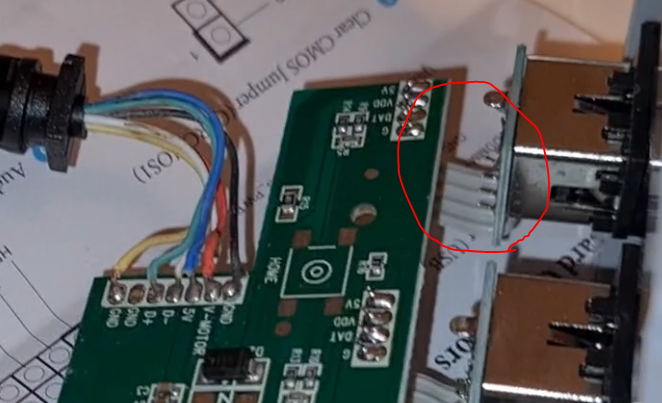
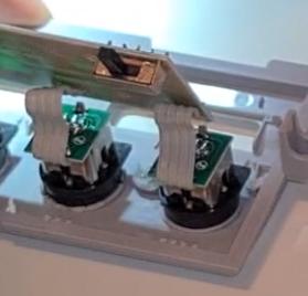
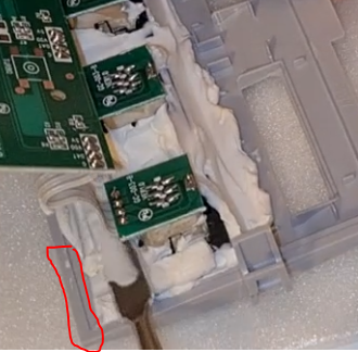
As you can see within the highlighted circle, we find a flexible connection between the ports and the adapter board. That’s exactly what we need!
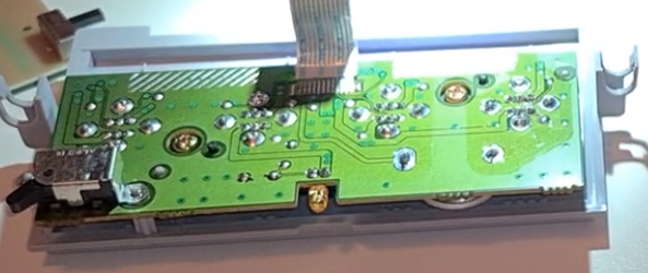
First, we want to remove the existing ports from the case. We remove the two screws and pull out the board as well as all four black ports.
Once we removed everything we should be left with the following part.
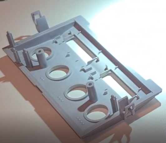
As you can see, we have a few plastic standoffs/mounting-points that would interfere while we work on the new ports. Therefore, we want to Dremel/melt them away. (Note: Do not remove the clamps on the outer left and outer right side of the housing!)
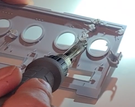
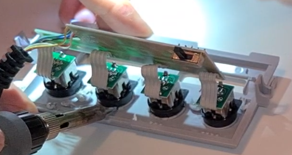
As we don’t have any kind of mounting mechanism for the new ports and they need to be very durable to handle the pressure that comes from plugging and unplugging different controllers, gluing is not the best option here. Therefore, we want to melt the new controller ports directly to the plastic of the controller port housing joining them permanently together. This needs to be done very carefully! We have to align the black ports on the grey housing of the original black ports as centered as possible otherwise the controller won’t fit.
Double check if the port is aligned correctly by turning it around. This helps finding the most centered positioning. The new ports need to be as centered on the grey port openings as possible! Also, we need to make sure to keep the original ordering of the ports. (Don't melt the actual adapter port 4 to the first port at the grey housing! This would mean that you later have to use the fourth/last port at the grey front in order to plug in the first controller. Just make sure that adapter port 1 goes to port 1 like indicated on the housing.)
As seen on the picture above the ports are upside down placed. This was a small mistake which results in having to plug the controller in upside down and messing up the correct odering of ports 1-4. However, there should be no problem within the build aligning them in the correct orientation doing it right like they should be! (Having the ports upside down also should not harm the build but you will have to swap the game configuration within dolphin. e.g.: Controller Profile 1 would now point to the fourth controller and vice versa.)
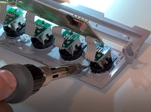
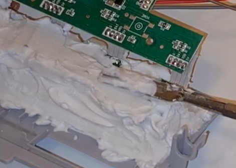
Now we put a small soldering tip on our soldering iron. We carefully melt completely around the black plastic of the ports while also touching/melting the grey plastic of the housing on which the black port lies at the same time. Be very careful not to melt through something or too much! At the same time, we need to make sure we melted enough plastic material together to get the most durability out of it. However better go the safe way here!
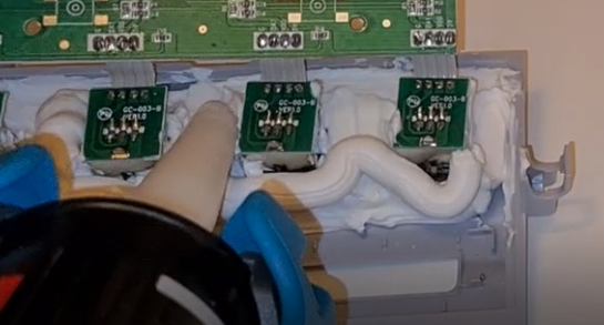
We should now have a first strong connection between the new ports and the original housing. But as our melted connection is relatively small and to be absolutely failsafe, we now apply Power Assembly Adhesive around our ports and the housing for them. Make sure to add glue all around the ports and as much as you can. However, make sure that the glue does not cover the flexible wire connection from the ports to the adapter board. Also, the glue should not get onto the frame of the housing. (Highlighted in red.) I recommend using a spatula to apply some pressure to the glue and removing the glue that might be too much or would block something and to apply everything evenly spreading the glue across the components. Note: Make sure the glue does not stand off to high as it could interfere with the motherboard or the closing process of the case. The maximum height for the glue is the height of the actual black ports like seen on the last picture.
Now the glue needs to harden for at least twenty-four hours.
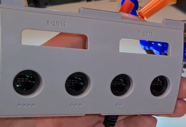
We should new have new ports within the original controller port housing with a very strong connection. We should now be able to physically plug in a controller through the original plastic housing.
Side note: If you want to keep the Memory card slot covers you need to get them from the teared down parts of the original system. I don’t recommend melting them to the controller housing as the plastic is very thin and might get uneven at the backside of it. gluing them on with some hot glue might be the best choice here. (Hold the covers with your fingers from one side at the controller housing and add the glue from the other side. Try to align them as good and even as possible.)