Home
#A
Quite a bit, actually!
Welcome to the HRT Keypad Contest information page.

Thanks again to Gateway Electronics for supplying the grand prize for our contest!
During the summer of 2012 co-workers Andrew and Nathan ran across some Hall Research KP-2B keypads that were being thrown away. The idea of using the keypads' enclosures for future home projects was mentioned, so the eleven keypads were salvaged from the trash. Curiosity got the better of Andrew, and he opened one of them. Inside was an 8051-compatible, 20-pin microcontroller, several octal latches, an RS-232 transceiver, a reset component, a crystal, and a bunch of passives.

The idea of reprogramming the 8051-compatible microcontroller was quickly abandoned after realizing the difficulty of developing for such a device. It was noted, however, that the power, ground, and clock pins were in the same position as that of the popular Atmel ATtiny2313. At some point one of them mentioned the idea of having a contest, but doing so would require a programmer for each of the keypads, so nothing serious came of it immediately.
Later that year Andrew was finishing work on his home-built CNC machine and wanted to try the new machine's ability with milling a PCB. He came upon the idea of creating programmers for the ATtiny2313 and distributing them with the keypad retrofitted with an ATtiny2313 for the purpose of having a competition.
New artwork was created for a single-sided, milled version of the USBtinyISP. The programmers were milled, soldered and tested. The reset device was removed from the keypad's circuit, and the 8051 MCU was replaced with the ATtiny2313.

On December 13, 2012, Andrew presented a talk at his work to a group of mostly software engineers on how to program a microcontroller, how the hardware worked, and details of the contest. The attendees were offered a development kit at no cost, on the condition that they return the kit if they didn't complete an entry for the contest. Additionally, a couple of simple example projects were released to aid the participants' understanding of how to interface the hardware (see here and here).
Additionally, Gateway Electronics provided the grand prize for the competition, a $25 merchandise certificate! If you aren't familiar with them, Gateway Electronics (or just "Gateway", as all the cool kids call it) is St. Louis's electronic components, hobbyist, and DIY repair supplies retail store. Located near Westport Plaza, you can visit them to find all sorts of components from LEDs, resistors, capacitors, connectors, switches, enclosures, motors, relays, robot parts, and all sorts of wires and cables (pre-made, packaged, by-the-spool, and by-the-foot) to electronics kits, tools, power supplies and test equipment, prototyping supplies, and also an entire section of miscellaneous mystery items--you never know what you'll find when perusing the back aisle!
After the contest had concluded, on January 15, 2013 a meeting was held where a demonstration of the projects occurred. The participants who completed a project voted for the winner. The contest entries have been released as open source and have been made available in this github repository.
Of the original eleven keypads, seven people submitted a complete project. The winning project, and recipient of the $25 merchandise certificate from Gateway Electronics, was the Internet Radio Control Panel. The runner-up project, and recipient of the SARduino644 v1.0 circuit board from Space Age Robotics, was the "Capture" game and Keypad Emulator. Thanks again to Gateway Electronics and Space Age Robotics. You guys rock!
The Internet Radio Control Panel is a simple serial output interface for button press and release events. The fuses on the MCU were altered to use the on-board 11.0592 MHz crystal, which divides nicely for a 38400 bps serial connection.
The software is as simple as possible, sending 'P#' events for each button (0-9) when pressed, and 'R#' when released, when changes made it past a 1ms debounce period. For some unknown reason, the author was unsuccessful at getting UART receive to work. When a button press is identified, the corresponding LED is lit and remains lit until some other button is pressed or power is removed.
At the other end of the serial connection is a TP-Link WR703N wireless router running OpenWRT and mpd with a USB sound card, for playing internet radio stations (primarily, stations from SomaFM.com). The router is running a script parsing incoming button press events and playing preselected stations. Pressing button 10 stops sthe music.
Because the author didn't have a working proper RS-232 adapter interface available, he made a custom connector to power the device with 5 volts and use TTL levels for the serial connection, rather than RS-232 levels. The custom adaptor injected the DB-9 cable with 5V power on pin 1, ground on pin 5, Tx on pin 2 and Rx on pin 3. Tx and Rx came directly from the MCU, wired to the input side of the Sipex RS-232 level converter. At the other end of the serial line is a basic FTDI USB-Serial breakout board hacked onto another DB-9 connector.
The control panel was a big hit with the wife and the 3-year old, who can now select favorite stations without using SSH.
Have a look at the hastily compiled demonstration video!
Video demonstration can be seen here.
Game Play for "Capture" in HRT Model KP-2B keypad.
- To start a round, press a button, it can take two presses.
- A light will start from the top right or left and sweep down to the opposite bottom led.
- Capture the light at position 7, 8, or 9 by pressing the button 9 or 10 in the direction of travel.
- If the light starts at the top left use the bottom right button, if it starts at the top right use the bottom left button
Scoring:
- Capturing at 8 gives 2 points
- Capturing at 7 or 9 gives 1 point
- Any other position is 0 points and you loose a turn, you get 3 turns per try.
- If you beat the high score all LEDs blink and the score is displayed.
- A high score is prefixed by both rows of LEDs sweeping from the left to the right.
- At the end of a round the current score is displayed prefixed by a sweep from the right with both rows of LEDs and the score is displayed three times.
- Score is displayed 10's first after the lower sweep to 10, 1's second after the upper sweep to 1
- In the case of a 0 no LEDs are displayed for that digit, in the case of 100 something the LED 10 will illuminate when tens are displayed.
- The high score can be cleared by holding button 1 and 5 when a score starts to be displayed.
The emulator is an API and GUI that allows the source code to be compiled, tested, and debugged on the desktop. It is an incomplete source compatible emulator for the keypad hardware. With minor changes such as disabling the inline assembly, which would only work for the AVR microcontroller. It is complete enough that it was able to compile and run all but one other contestant entries, because it made use of hardware the other devices didn't. The emulation is accomplished by making each register be a C++ object and using operator overloading to turn what would be memory mapped io accesses into object function calls, which could then set LEDs, read buttons, toggle the speaker pins, or setup the timer/counters and interrupts. I ended up spending much more time on the emulation software than the game competition entry. The emulation's execution timing has the most difference between the emulation and hardware, and that was most evident in the sound generation. Toggling the generation of high vs low square sound waves lets you hear that sound is being generated, but it sounds bad compared to the hardware, which sounds bad compared to a modern sound card, but the goal of being able to develop and debug on the system was met.
Video demonstration can be seen here.
This is a simple program that will take a variable number of button presses, and then repeat that pattern with the corresponding LEDs until any button is pressed. Below is the basic operational flow.
(1) On application of power/reset, all of the LEDs are turned on then off one after another from 1 to 10. This is then repeated.
(2) All of the LEDs flash twice.
(3) The code then waits for a user to select one of the 10 buttons. The number of the button represents the number of entries in the pattern. Call this number N.
(4) After the number of entries is selected, all of the LEDs flash once to indicate that the user can begin entering a button pattern.
(5) Once the user has pressed N buttons, the LEDs will be lit in that pattern, and will repeat indefinitely.
(6) If the user hits any button, the pattern will stop and all LEDs will flash twice. Then go back to step (3).
Video demonstration can be seen here.
This contest entry is a memory game, similar to the 1970's electronic game "Computer Perfection" by Lakeside.
The goal of the single-player game is to press the buttons in the correct order. The order changes from round to round, and is revealed to the player at the beginning of each round during a "preview" mode. When in preview mode, the user presses each button once (starting at button 1, then 2, and so on) and the game will light up the button that (later on) will activate the corresponding light. Once the preview is finished, gameplay begins. The player must then press the button that activates light 1, then the button that activates light 2, and so forth. Once all the lights are lit, the gameplay ends and the player is shown their score. The score is determined by how many button presses were required to solve the game, and the lowest score wins.
Video demonstration can be seen here.
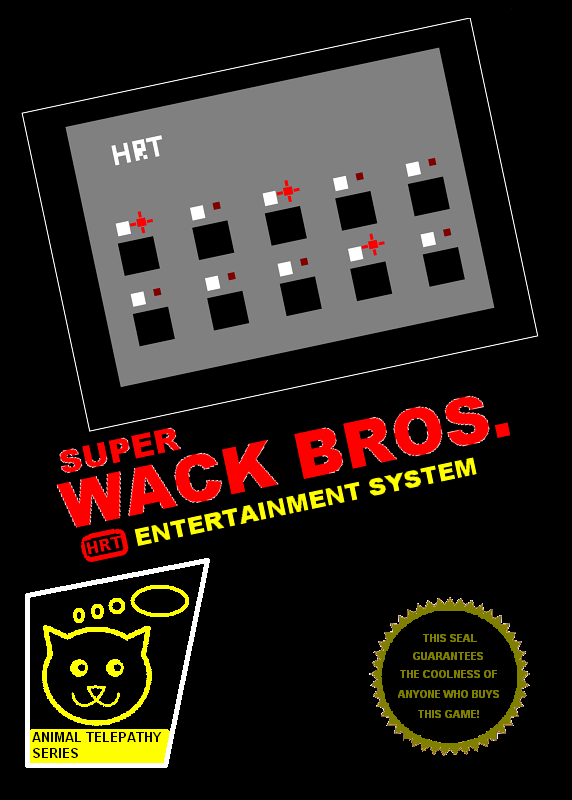
Super Wack Bros. is a two-player head-to-head super-wack whack-a-mole game. The players each have to guard four mole holes, and win by getting ahead of their opponent by reacting the fastest. The game can use the optional speaker to play sound effects and in-game music inspired by music from the classic Dig-Dug game. As the game progresses the game play and music speed-up, increasing the tension. A player wins when they have whacked five more moles than their opponent.
The slides of the presentation given during the demonstration meeting can be seen here.
Box art inspired by the Nintendo Entertainment System's launch game series, commonly called the black box games:


Larger versions can be seen here: Front and Back
Bongo Hero is a one person game modeled after the popular guitar game. The game has three user selectable levels of increasing difficulty that are selectable when power is applied. Unlike all the other entries submitted for our contest, Bongo Hero is played with the keypad controller rotated 90 degrees from normal. For gameplay, lights "fall" from button 1 to button 5 for the right "bongo", and from button 6 to 10 for the left "bongo". When the lights reach the bottom row, players must hit the appropriate "bongo" (either button 5 or 10) in time with the lights. When the bongos are hit in tempo, all lights in that row illuminate for 0.1sec to indicate a proper hit. The sequence and tempo for each level are programmed into the software. Level 1 is a basic, slow rhythm. Level 2 is 'Back in Black'. Level 3 is 'Rock and Roll'. After each level completes, the software automatically returns to the level selection menu.
The software is written using timers to control the light progression. This makes controlling tempo extremely easy, and accurate. The sequence of hits is programmed as two separate byte-arrays for each bongo. The sequence is played using nested for-loops, and bit-shift arithmetic. The inner-most for loop continuously reads from the switches until the timer indicates the next note should be played.
The author considered adding two Photo-Trasistors and Infrared LEDs to the side of the device in order to sense hand movement using an actual set of bongos, but ultimately, it was decided that he wasn't getting paid enough for that.
Sorry, no description or demonstration is available. The source code can be found here.
The fuses default to the built in 8Mhz oscillator and divide that clock by 8 for a CPU clock rate of 1MHz. The fuses can be reset to start up at a faster clock rate, or the software can reset the clock divider.
If you have an updated repository with the cpu_clock sample and header,
#include "../../include/ATtiny2313_clock.h"
int main()
{
        CPU_PRESCALE(inline_cpu_hz_to_prescale(F_CPU));
}
Otherwise, for 8MHz,
#define CPU_PRESCALE(n) \
{uint8_t __read_hz=n; CLKPR = _BV(CLKPCE); CLKPR = __read_hz;}
int main()
{
        CPU_PRESCALE(0)
}
Either way the cost is 6 bytes of program code.
Attention: Did you remove the ribbon cable from the main board of the keypad and forget it's correct orientation for reattachment? Wire #1 (the one with the red stripe on it) is closest to the MCU. Wire #10 (the wire on the opposite edge of the ribbon cable from the red one) is closest to the TO-220 voltage regulator.
Requires:
- Soldering iron, solder and basic soldering skills
- DC power jack
- Drill and bit
- A tools to cut and strip wire
- Spare AC adapter
- Tape
An AC adapter can be used instead of a battery. One way to do it is to drill a hole in the back cover plate for a DC power jack--2.1mm is a common size that will work with that extra AC adapter you haven't thrown away yet.

According to the voltage regulator's datasheet the AC adapter should output DC voltage, anywhere from 5.6 (should probably say "6.0" just to be on the safe side) to 26 volts. Note the polarity (it seems like most adapters have the outside of the barrel as negative, but some have the outside as positive). To maintain the other possible capabilities of the DB-9 connector, cut only wire #1 (the one with the red line) and connect the side going to the board to the positive terminal of the power jack (leave the end of that wire going to the DB-9 unconnected, but put a piece of tape on it. Splice a wire onto wire #10 (the one on the opposite edge of the ribbon cable) and connect that wire to the negative terminal of the power jack.
Requires:
- Soldering iron, solder and basic soldering skills
- A female DB-9 connector (or sacrifice the provided 9V power supply)
- Maybe tools to cut and strip wire
- A small speaker (electromagnetic voice coil or piezo-electric)
- Epoxy if you want to get fancy
Audio can be played with a speaker add-on connected through the DB-9 port. One way to do it is to solder an audio transducer directly to pins 3 and 4 of a female DB-9 connector. Pin 3 of the DB-9 is indirectly (through the RS-232 transceiver) driven by the MCU's PD1 and pin 4 of the DB-9 by the MCU's PD6. See Nathan's example code for a software example to make square-wave music with this add-on.
Note the gender and orientation.

Important note: If you try this, either remove the power jumper from the USBtinyISP programmer, or remove the external power from the keypad (whether that be a 9V battery or an AC adapter).
Note: The author has only tried this with an STK500 programmer, and has not tried this with a USBtinyISP programmer (the type of programmer supplied with the dev kit. If you try this and it works, be sure to note that here. That being said, the author guesses that the USBtinyISP will be able to program the keypad in-circuit.
The advantage of in-system programming is simple for the keypad: You don't have to pull the MCU out of the keypad and insert it into the programmer to program it and then pull it back out of the programmer and put it back in the keypad to test it.
In-system programming can be done in at least two different ways:
- Buy (no, they aren't cheap) or pull out of the trash, a chip test clip.

- Solder wires directly to the MCU. If doing this, solder the wires to the top of the necessary pins, and do it with the MCU on it back (pins sticking up) to discourage the solder from flowing towards the tips of the pins as you're going to then put the MCU back in its original socket. As for which pins, I'll leave that as an exercise for the reader, but if you look at the target board, you are going to be copying that.
It was mentioned that the acid in fingerprints can speed oxidation of the copper plate. Two solutions were presented, one was getting a case for the programmer. For the other clear coat was mentioned. I did the clear coat with some spray paint enamel I had on hand. Here are the before and after shots. Just before I used some rubbing alcohol on a cotton ball (which left fuzz behind), and then used a patch of denim with distilled water, and an air compressor to try to get the fuzz off and dried it. I'm not sure how recommended that procedure is. I covered the holes with tape from the top, then covered the entire top with tape. I did two layers 1/2 day apart, then let it sit for two days and it still works. The bottom looks very nice and sharp. The top not so much, I haven't decided if the paint leaked in just through the tape or if it came in through the holes in the circuit board, and probably both, so it looks a little sloppy, but that bottom sure looks good.
