Can't flash Tasmota on Sonoff Basic #2344
Comments
|
If u plug in the ftdi, does the 2 green smds on the board flash once shortly while connecting to usb? RX<->TX TX<->RX always. if u tried to flash without DOUT modus in arduino IDE, maybe the devices is damaged. sync fail is a RX TX failure, you sid you tried another cables, but try another again.
another note:
as soon as you do not solder them, you are leaved foryourself. its not safe that "holding" them in place is connected. you wrote by yourself:
which also says, the connection of vcc an gnd is bad as fuck. if vcc and GND is given, the LED should blink (if the orginal fw is not damaged till now). you said you checked the vcc output, pls check the voltage of the VCC pin on the flasher and write it here. best would be to use another pc, maybe a windows one. if you can say you can flash with the windows one, you need to find the failure on the mac side (usb hub, usb-c voltage too low, secruity issue, wrong driver or not correct installed). |

|
More to add: connect the flasher with the sonoff, than hold the button down and plug in usb with the other hand. The button could be defect too and not connecting GPIO0 to gnd. |
|
in your esptool description you did not use DOUT, too... should be: |
|
Atom detected COM5 you used i suggest to stay by atom with platformIO, its the userfriendliest solution, selects correct port and dout by itsself. |
|
@reloxx13: Thanks so much for your follow up. Will respond to each point here.
Yes, there are 2-3 quick flashes of those LEDs when the cable is first plugged in.
I've tried multiple Dupont cables and two different Mini-USB cables with the same result.
Not sure what you mean by the first comment, but the voltage is being applied correctly (measured by multimeter). I've seen multiple YouTube videos of people holding the PINs in place during flashing without issue. To your last point, the original firmware is likely gone due to the SonOTA experiment.
The voltage at the male end of the Dupont cables (with the female ends connected to the FTDI adapter) reads 3.35v.
That's a good point. Sadly, I don't have a Windows PC, but I'll see if I can drum one up. What about Linux?
I don't believe the Sonoff button is defective. This is a brand new device and prior to experimenting with SonOTA (i.e., with the original Sonoff firmware), the relay opened and closed with each button press. I can confirm that I am pressing the button straight down and hear it click.
Apologies, the output from the original post had an incorrect port – I've updated the PlatformIO log and put it below. Note that Understand that in the case of |
|
I don't see an external regulator on that board, which means they are probably using the internal LDO of the FT232R, which is rated as follows: +3.3V output from integrated LDO regulator. This pin should be decoupled to ground using a 100nF capacitor. The purpose of this output is to provide the internal +3.3V supply to the USB transceiver cell and the internal 1.5kΩ pull up resistor on USBDP. Up to 50mA can be drawn from this pin to power external logic if required. This pin can also be used to supply the VCCIO pin. Notice the up to 50mA part. That is not enough to power an esp8266. The converter I have used to put USB VBUS (typically 5V) out on VCC. I used that until I actually measured it and saw what it was doing (it can damage an esp8266, though I didn't have that problem). I now have a regulator taking the 5V from USB down to 3V3 for the esp8266. I suggest using a NodeMCU or Wemos D1 Mini to get experience with the flashing process before trying it on a Sonoff. Once you have verified the software part is working, you can figure out the secret handshake to get the hardware working. |
|
Ah, great catch, @Frogmore42. I’ve flashed Tasmota onto several D1 Minis, so I’m familiar with the process. Given your feedback, I think I’ll find another way to power the Sonoff (perhaps through a 12v barrel supply, converted down to 3.3v, off a breadboard) and just use TX and RX on the FTDI converter. I’ll report back with what I find! |
|
The printouts above shows that esp might be not in flash mode, e.g. If possible check GPIO0=GND and GPIO2=3.3V during startup - that's flash mode (beside GPIO15, must be also GND) - to exclude any side problem do not assume button=GPIO0 (anyhow), check this on ESP |
|
@Frogmore42 is the winner: my FTDI converter wasn't delivering enough current to power the Sonoff long enough to flash. I thought about building a Rube Goldberg-esque contraption with a breadboard and 12v-3.3v barrel power converter, but then I remembered this YouTube video and built a simple FTDI converter (with ample current) from a spare Arduino UNO:
These were my steps:
And that's that! Thanks, all, for your help! |

|
i just got a batch of 4... i thought they would flash just like the previous four, but there has been some variety of hardware change... in the arduino settings options I had to set to dout, and in the software I removed all references to "Serial"... everything works perfectly after that... can't tell you why the serial monitor was causing the problem, but that is what it turned out to be... |
|
don't put the baud rate in. |
|
I just plug the pins temporarily for flashing in the holes and it works but the last batch of sonoff basics I received have the holes soldered up now for some unknown reason so I spent time de-soldering them and most worked except one and I had to solder header pins on that one. Why would they start soldering up the holes? |
|
@ubeaut Me too! Latest batch had the GPIO pins soldered in and required me to heat them up and suck the solder out. No way to prove this, but I wonder if they’re trying to prevent what we’re doing (flashing over their firmware). |
|
If they do their sales will drop......dramatically!
…On 5 May 2018 at 11:18, Aaron Bach ***@***.***> wrote:
@ubeaut <https://github.com/ubeaut> Me too! Latest batch had the GPIO
pins soldered in and required me to heat them up and suck the solder out.
No way to prove this, but I wonder if they’re trying to prevent what we’re
doing (flashing over their firmware).
—
You are receiving this because you were mentioned.
Reply to this email directly, view it on GitHub
<#2344 (comment)>,
or mute the thread
<https://github.com/notifications/unsubscribe-auth/AbSpjeXh3nbqJpXIUVn9Yv_qkbL5RmGdks5tvP32gaJpZM4TFVXR>
.
|
|
Same here ... I've got about 25 sonoff ( 15 Basic, 2 Th, 2 4Channel..., 3 Touch) and could easily flash all of them using an Arduino IDE... Questions for the team here:
|
|
My 5 cents PLUG my FTD1232 into it Then I press the black button plug it into the USB into computer count to 10 take finger off button then I load FlashESP8266.exe select the com port them select the bin which in the same dir as FlashESP8266.exe and hit flash done Have done for the last 6 sonoff and it always work for me |
|
Further (imperfect) progress |
|
It is VERY DANGEROUS! DO NOT CONNECT FTDI WHILE MAINS IS ALSO CONNECTED!!!! YOU CAN BE ELECTROCUTED!!!! FTDI provide the 3.3v needed for the esp8266 If your FTDI can not provide enough power, please use an extern 3.3v supply |
|
After much frustration, I was able to flash several of the new 'sonoff basic' (with date 2017-05-05 on board), by following these steps:
SUCCESS! I wasn't able to flash them directly with Arduino or platformio! |
|
Every now and then I get a new batch of various Sonoff devices and my previously working system does not flash them due to various reasons not directly controlled by me. I have a long txt file with black magic tricks to remind myself. And it worked! BTW I use an external 3.3V supply as I don't trust those FTDI adapters. |
|
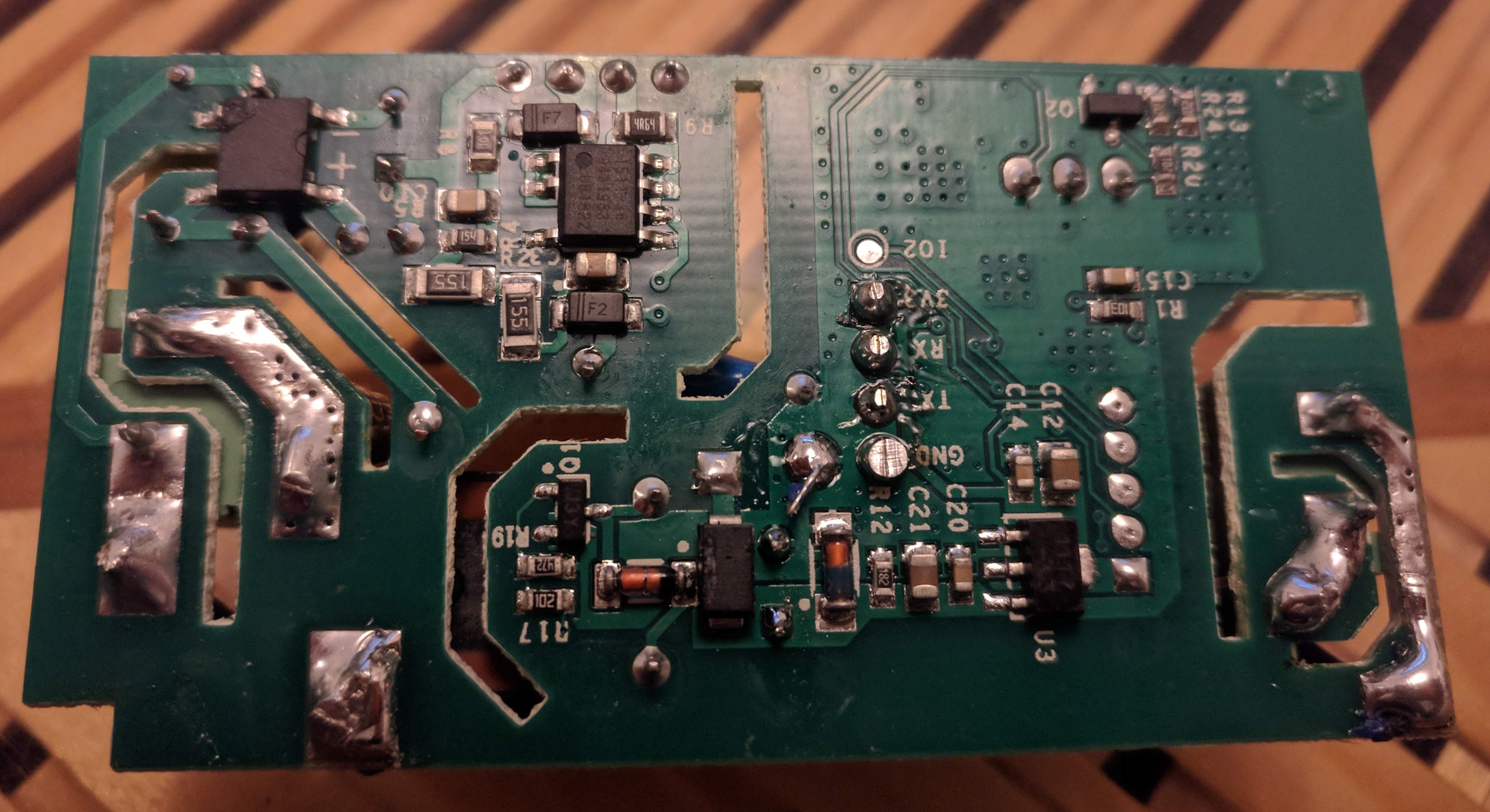
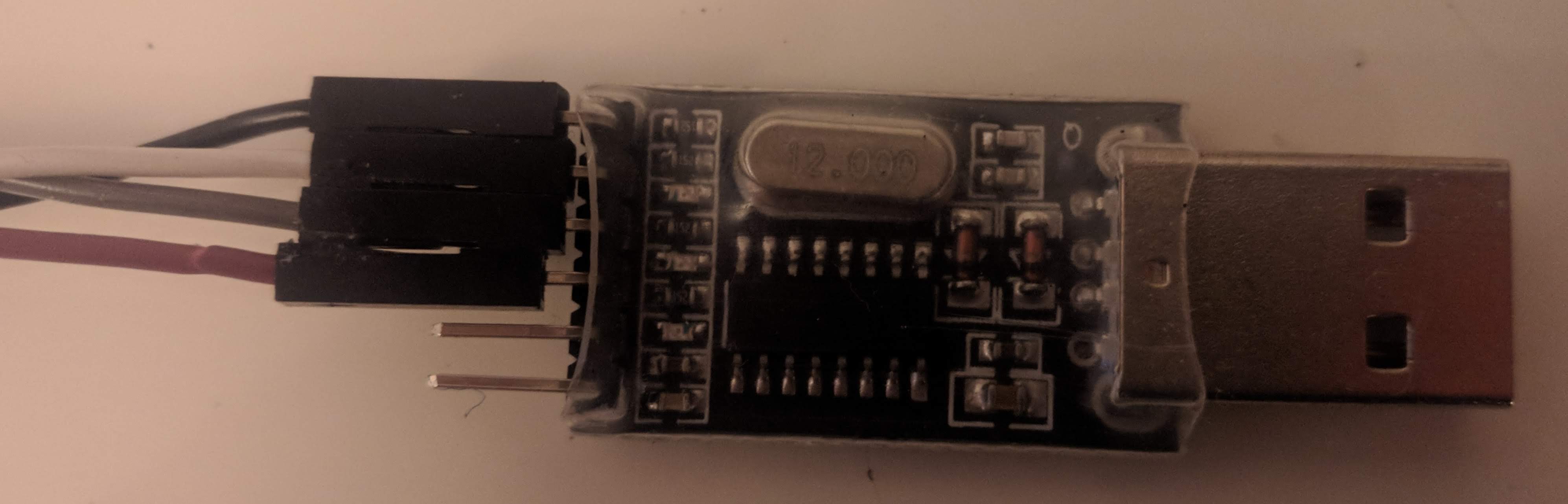
I managed to flash my new Sonoff Basic RF R2 Power switches using vscode on a Fdora linux computer and a CH340G USB board. At first I followed the instructions on https://github.com/arendst/Sonoff-Tasmota/wiki/Sonoff-Basic, but I always ended with this same error message: I found out that my vscode session (runs as a normal Linux user without root privileges) did not have the proper permissions to connect to the /dev/ttyUSB0 device. So I tied this: I still did not work. I found out that the permissions got lost when I connected the 3v3 wire. The final solution was to grant the permissions again after connecting the 3v3 wire. My Sonoff Basic RF R2 Power:
The preparations I took to flash successfully:
The steps I took to flash successfully:
My CH340G USB:
Cable connected to the sonoff: May it is useful for other to mention this /dev/ttyUSB0 permissions solution in the documentation somewhere? Question: How can I resolve the /dev/ttyUSB0 permissions issue permanent, without the need to apply the permissions every time I reconnect to a Sonoff using the USB CH340G? |


|
To make the /dev/ttyUSB0 permissions permanent.
Put your user in the dialout group.
vi /etc/group
dialout:x:20:youruserid
save the group file
log out and log back in
type id and hit returnYOu should see you are now in the dialout group
…On Thu, 3 Jan 2019 at 20:40, Ted Sluis ***@***.***> wrote:
I managed to flash my new Sonoff Basic RF R2 Power switches using vscode
on a Fdora linux computer and a CH340G USB board.
At first I followed the instructions on
https://github.com/arendst/Sonoff-Tasmota/wiki/Sonoff-Basic, but I always
ended with this same error message:
Compiling .pioenvs/sonoff-basic/src/sonoff.ino.cpp.o
Linking .pioenvs/sonoff-basic/firmware.elf
Retrieving maximum program size .pioenvs/sonoff-basic/firmware.elf
Building .pioenvs/sonoff-basic/firmware.bin
Checking size .pioenvs/sonoff-basic/firmware.elf
Memory Usage -> http://bit.ly/pio-memory-usage
DATA:    [======    ]  55.4% (used 45380 bytes from 81920 bytes)
PROGRAM: [====      ]  43.9% (used 449140 bytes from 1023984 bytes)
Configuring upload protocol...
Looking for upload port...
Use manually specified: /dev/ttyUSB0
Uploading .pioenvs/sonoff-basic/firmware.bin
error: cannot access /dev/ttyUSB0

error: espcomm_open failed
error: espcomm_upload_mem failed
I found out that my vscode session (runs as a normal Linux user without
root privileges) did not have the proper permissions to connect to the
/dev/ttyUSB0 device. So I tied this:
***@***.*** ~]# ls -lha /dev/ttyUSB*
crw-rw----. 1 root dialout 188, 0 3 jan 07:35 /dev/ttyUSB0
***@***.*** ~]# chmod 777 /dev/ttyUSB0
***@***.*** ~]# ls -lha /dev/ttyUSB*
crwxrwxrwx. 1 root dialout 188, 0 3 jan 07:36 /dev/ttyUSB0
I still did not work. I found out that the permissions got lost when I
connected the 3v3 wire. The final solution was to grant the permissions
again after connecting the 3v3 wire.
My Sonoff Basic RF R2 Power:
<https://raw.githubusercontent.com/tedsluis/Home-AssistantConfig/master/images/sonoff_front.jpg>
<https://raw.githubusercontent.com/tedsluis/Home-AssistantConfig/master/images/sonoff_back.jpg>
The preparations I took to flash successfully:
- install platformIO plugin in vscode
- solder a 4 pin socket on the sonoff board
- connect the sonoff with the CH340G: GND-GND, Txd-RxD, RxD-TxD,
3v3-3v3
- download and unzipped Sonoff-Tasmota Source code
<https://github.com/arendst/Sonoff-Tasmota/releases> and opened it in
vscode
- edit platformio.ini
<https://github.com/arendst/Sonoff-Tasmota/blob/master/platformio.ini>
and select the sonoff-basic environment and configure upload_port =
/dev/ttyUSB0
- edit my_user_config.h
<https://github.com/arendst/Sonoff-Tasmota/blob/development/sonoff/my_user_config.h>
and configure WFI ssid/password, ip address, gateway, dns, etc
The steps I took to flash successfully:
- disconnect the CH340G usb from the computer
- connect all the wires, except the 3v3.
- press and hold down the button on the sonoff board.
- insert the CG340G USB into the computer
- execute: sudo chmod 777 /dev/ttyUSB0
- connect the 3v3
- again execute: sudo chmod 777 /dev/ttyUSB0
- let go the button on the sonoff board
- wait 3 seconds
- Selected "Upload" from the menu to flash the firmware.
Compiling .pioenvs/sonoff-basic/src/sonoff.ino.cpp.o
Linking .pioenvs/sonoff-basic/firmware.elf
Retrieving maximum program size .pioenvs/sonoff-basic/firmware.elf
Building .pioenvs/sonoff-basic/firmware.bin
Checking size .pioenvs/sonoff-basic/firmware.elf
Memory Usage -> http://bit.ly/pio-memory-usage
DATA:    [======    ]  55.4% (used 45380 bytes from 81920 bytes)
PROGRAM: [====      ]  43.9% (used 449140 bytes from 1023984 bytes)
Configuring upload protocol...
Looking for upload port...
Use manually specified: /dev/ttyUSB0
Uploading .pioenvs/sonoff-basic/firmware.bin
Uploading 453280 bytes from .pioenvs/sonoff-basic/firmware.bin to flash at 0x00000000
................................................................................ [ 18% ]
................................................................................ [ 36% ]
................................................................................ [ 54% ]
................................................................................ [ 72% ]
................................................................................ [ 90% ]
...........................................                                      [ 100% ]
==== [SUCCESS] Took 57.81 seconds =====
My CH340G USB:
<https://raw.githubusercontent.com/tedsluis/Home-AssistantConfig/master/images/ch340g_front.jpg>
<https://raw.githubusercontent.com/tedsluis/Home-AssistantConfig/master/images/ch340g_back.jpg>
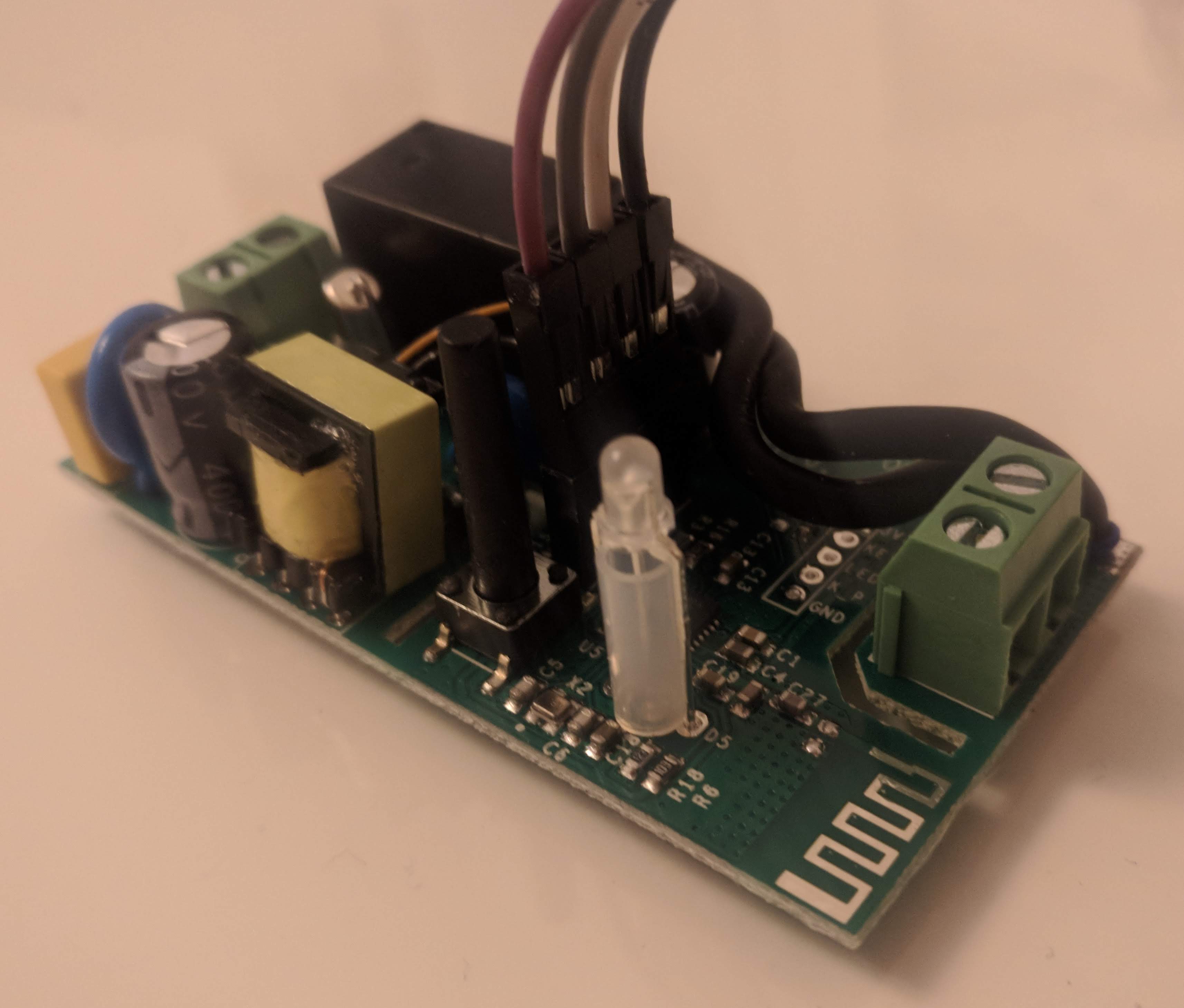
Cable connected to the sonoff:
<https://raw.githubusercontent.com/tedsluis/Home-AssistantConfig/master/images/sonoff_cable.jpg>
May it is useful for other to mention this /dev/ttyUSB0 permissions
solution in the documentation somewhere?
Question: How can I resolve the /dev/ttyUSB0 permissions issue permanent,
without the need to apply the permissions every time I reconnect to a
Sonoff using the USB CH340G?
—
You are receiving this because you were mentioned.
Reply to this email directly, view it on GitHub
<#2344 (comment)>,
or mute the thread
<https://github.com/notifications/unsubscribe-auth/AbSpjSodRVYh9noPx1Ig-LFWZoXAuQRdks5u_dAbgaJpZM4TFVXR>
.
|
This comment has been minimized.
This comment has been minimized.
This comment has been minimized.
This comment has been minimized.
This comment has been minimized.
This comment has been minimized.
This comment has been minimized.
This comment has been minimized.
This comment has been minimized.
This comment has been minimized.
This comment has been minimized.
This comment has been minimized.
|
You really ought to strongly consider using TASMOTA. That aside, if you have a binary (regardless of what firmware it is) you can use ESPEasy Mega to upload the binary to the device. I find the method described in Dr. Zzs tutorial pretty foolproof. Mike |
|
FYI, I finally got flashing to work. Turns out I needed to downgrade my FTDI driver to 2.10.0.0. Thanks all. |
|
For posteriety (eg future googlers), I spent an hour or two on this, even replaced a device in case I let the smoke out of it with an accidental 5V connection and then an intentional 5V connection to a Sonoff Pow R2, as I thought maybe my FTDI wasn't providing enough power. .. it wasn't providing enough power. After getting a Sparkfun Beefy 3, it worked on the first try. I should have done it sooner and saved myself time. Either whip up a good 3.3v power supply or grab a FTDI that can supply enough power like the Beefy 3. |
|
A simple 100uF cap between 3.3V & GND helps a lot with FTDI.
El jue., 2 may. 2019 a las 15:28, Ted Timmons (<notifications@github.com>)
escribió:
… For posteriety (eg future googlers), I spent an hour or two on this, even
replaced a device in case I let the smoke out of it with an accidental 5V
connection and then an intentional 5V connection to a Sonoff Pow R2, as I
thought maybe my FTDI wasn't providing enough power.
.. it wasn't providing enough power.
After getting a Sparkfun Beefy 3 <https://www.sparkfun.com/products/13746>,
it worked on the first try. I should have done it sooner and saved myself
time.
—
You are receiving this because you are subscribed to this thread.
Reply to this email directly, view it on GitHub
<#2344 (comment)>,
or mute the thread
<https://github.com/notifications/unsubscribe-auth/ACXBW4MWXWOO2PSHF7YSNBTPTMXFXANCNFSM4EYVKXIQ>
.
|
|
That may be, but if you're supplying power to a Sonoff through a FTDI, it's very likely to not have enough power, as others in this thread have already noted. For instance, the FT232R's built-in LDO supplies "up to 50mA". That's enough to run an 8266 at idle, but certainly not when transmitting. |
|
Alas, increasing voltage doesn't necessarily mean more available power to the device. Usually available power (Watts) available from the FTDI is "capped". Increasing the voltage just means less current and vice versa. A CH340 based serial adapter will improve the available power situation. |
|
Yep, voltage was a mistake. It was a hope that I'd be (a) grabbing it from the USB power, not through the chip and (b) it wouldn't let any magic smoke out. |
|
I had the same problem. I programmed 12 sonoffs and only a half of them had good connection to COM port. I tried a lot, that was written at forums. But the solution i found was - to solder wires directly from USB-TTL card into Sonoff board!!! Do not use any connectors. May be there is resistance in plastic case of connector, or may be there is bad conact. |
I,ve just signed up. I am a complete newbie to sonoff and just wanted to say that after a day of trying various things to flash my sonoff , this turned out to be my issue too. |
|
I was also struggeling to flash a Sonoff Basic. I was using a cheap CH340 adaptor and connected the board with the 3.3V pin. (TX->RX, RX->TX, button pushed when powering up the device, first erase and then upload of the firmware) I used sveral tools for flashing, for example tasmotizer and pyflasher and the upload was even sometimes confirmed to be successfull, however the sonoff didn't do anything. In the end using the esptool.py helped. It showed that the MD5 checksum wasn't right. I then connected the sonoff board with the vcc pin instead of the 3.3V and it worked like a charm. Maybe the CH340 wasn't powerful enough or the cables were too long the mulitmeter showed less than 3V, and thus, using VCC (5V) did help in the end. Just wanted to let you guys know in case you are also struggeling |
|
Never connect sonnov Vcc to 5V. unless your CH340 was 3.3v device or was
wrong, 5V on sonoff vcc will destroy the esp chip
El jue., 30 ene. 2020 a las 13:11, moelfus (<notifications@github.com>)
escribió:
… I was also struggeling to flash a Sonoff Basic. I was using a cheap CH340
adaptor and connected the board with the 3.3V pin. (TX->RX, RX->TX, button
pushed when powering up the device, first erase and then upload of the
firmware) I used sveral tools for flashing, for example tasmotizer and
pyflasher and the upload was even sometimes confirmed to be successfull,
however the sonoff didn't do anything. In the end using the esptool.py
helped. It showed that the MD5 checksum wasn't right. I then connected the
sonoff board with the vcc pin instead of the 3.3V and it worked like a
charm. Maybe the CH340 wasn't powerful enough or the cables were too long
the mulitmeter showed less than 3V, and thus, using VCC (5V) did help in
the end. Just wanted to let you guys know in case you are also struggeling
—
You are receiving this because you commented.
Reply to this email directly, view it on GitHub
<#2344?email_source=notifications&email_token=ACXBW4IXD2N5K35AERFZE2TRAL34BA5CNFSM4EYVKXI2YY3PNVWWK3TUL52HS4DFVREXG43VMVBW63LNMVXHJKTDN5WW2ZLOORPWSZGOEKLR2NI#issuecomment-580328757>,
or unsubscribe
<https://github.com/notifications/unsubscribe-auth/ACXBW4MNRQR2VJLD5YH22YLRAL34BANCNFSM4EYVKXIQ>
.
|
|
@lalo-uy you are completly right! My mistake, I'm using one of the cheap CH340 which have three pins, 3V, 5V, and VCC. I used a multimeter and VCC delivers ~3.7 V. The device delivers enough power to flash a sonoff basic and sonoff touch, however is not sufficent enough for an S26 |
|
I also had several problems. In the end I realized that you need to have well-fixed connectors: |
Hi all – apologies for yet another "I can't flash" issue thread, but I've tried everything I can think of (and everything I've read in various other issues) and I just can't get it to work. I'm 99.9% certain this isn't a Tasmota issue, but given the expertise of everyone here, I'm hoping I can post everything I have and get your advice on how to proceed. I'm used to smashing through issues, so this is irking me. 😎
Thanks in advance for stomaching all this; again, I offer it for completeness and in the hope that someone smarter than I can offer advice.
Hardware
Sonoff
I'm using a Sonoff Basic. For reasons I'll share shortly, I assume this unit is using a firmware higher than 1.6.
FTDI Converter
I'm using a FT232RL FT232 FTDI USB to TTL 3.3V 5.5V Serial Adapter Module Download Cable for Mini Port (a mouthful!). I've confirmed that connecting a Mini USB port provides 3.3v across VCC and GND.
Computer
I'm using a MacBook Pro (13-inch, 2017, Four Thunderbolt 3 Ports) running macOS High Sierra 10.13.4. I've installed the VCP drivers for FTDI devices (per this comment) and can confirm (via
Apple > System Report > USB) that the MacBook recognizes the FTDI adapter when connected:It also appears as a loaded kext:
USB Hub
Because this generation of MacBook is USB-C-only, I connect the Mini USB cable via a USB-C hub. Can't imagine this matters, but including it for completeness.
Hardware Preparation Attempts
1. Via SonOTA
I first attempted to flash Tasmota via SonOTA (given that I've had success with it before). I got about 90% of the way through the process, but was halted at the last step (i.e., the "FinalStage" network). A comment on that project's issues page led me to believe that if I was having troubles, it might mean that I was using a Sonoff firmware higher than 1.6 and would need a manual flash.
I share this with you not to debug SonOTA, but to let you know that "something" was flashed onto the Sonoff during this process. I can tell because the process of holding down the Sonoff button and seeing the green LED flash consistently no longer occurs (indicating, I assume, that the "flash the firmware" functionality present in the original Sonoff firmware might be gone?).
Again, providing for completeness.
2. Via Serial Connection
Reading around, I deduced that I didn't specifically need to solder header pins onto the Sonoff; rather, I could use male-to-female Dupont cables:
I attempted flashing via three different tools:
esptool.pyFor each tool, I attempted a few different procedures, each with the same result (detailed in the next section). For completeness, these procedures are listed here.
Procedure 1
Procedure 2
Procedure 3
Procedure 4
– – –
In all cases, the Sonoff LED never came on (flashing or otherwise). Anecdotally, if I connect only the
VCC -> 3v3andGND -> GNDpins, the LED flashes for a bit, goes dark, goes solid for a bit, goes dark, etc.Flashing Attempts
1. Arduino IDE
Followed the Tasmota instructions for the Arduino IDE. After 9-10 seconds, the IDE returns the following error:
2. PlatformIO
Followed the PlatformIO instructions for the Arduino IDE. After 9-10 seconds, the IDE returns the following error:
3.
esptool.pyVersion 14.
esptool.pyVersion 2Using an idea I'd read elsewhere, I started
esptool.py, let it attempt to connect, then connected voltage to the Sonoff. As soon as voltage was connected, the stack trace below occurred.Alterations I Have Tried
TX -> RXandRX -> TXTX -> TXandRX -> RXAlterations I Haven't Tried
The text was updated successfully, but these errors were encountered: