-
Notifications
You must be signed in to change notification settings - Fork 29
New issue
Have a question about this project? Sign up for a free GitHub account to open an issue and contact its maintainers and the community.
By clicking “Sign up for GitHub”, you agree to our terms of service and privacy statement. We’ll occasionally send you account related emails.
Already on GitHub? Sign in to your account
Using swifitch with existing switches & 110v #6
Comments
|
Hi Alexander, I'm happy you like it ;) 1, I don't know about 110V but I think that HLK-PM01 is capable to run on 110V too. So it should be ok in US. 2, It's actually D2 and yes you can connect analog switch. What you need is L/N cables under switch to power Swifitch. It need to have both and N isn't always available under switches so it depends on your house wiring. 3, Wiring of analog switch is easy, just completely remove any high voltage wires from the analog switch and connect the contact to 3V3 from Swifitch to analog switch, output from analog switch to pin D2 and then bridge D2 and GND on Swifitch with 10k Ohm resistor which will pulldown the D2 pin to register correctly when analog switch is disconnected from 3V3. All the functionality should be in firmware itself, I have done the changes for my friend who has wiring so he could use it this way and he is happy with that. Thought it wasn't designed with analog switch in mind. Hope this is clear ;), otherwise let me know. BR, Martin |
|
Thanks for a quick reply! I will later remove one of the faceplates to figure out the current wiring and will post it here. Still a little bit unclear to me. for the 3. Thanks! I was thinking why not to connect D2 to the switch and the other end to the GND, and set D2 to INPUT_PULLUP in the firmware, I thought this way it will not require bridging and will be less wires :) I have recently connected a button to an arduino this way, correct me if Im wrong. |
|
Yes
… On Dec 10, 2017, at 9:23 AM, Martin Doubek ***@***.***> wrote:
So if I get it right you suggest this scheme and enabling INPUT_PULLUP option?
—
You are receiving this because you authored the thread.
Reply to this email directly, view it on GitHub, or mute the thread.
|
|
Also in the firmware it will require minor changes to compare digitalRead of D2, with LOW instead of HIGH
… On Dec 10, 2017, at 9:23 AM, Martin Doubek ***@***.***> wrote:
So if I get it right you suggest this scheme and enabling INPUT_PULLUP option?
—
You are receiving this because you authored the thread.
Reply to this email directly, view it on GitHub, or mute the thread.
|
|
OK if the change is just pinMode(D2,INPUT_PULLUP); and swapping LOW/HIGH I will do the change and test it. Will include the scheme too. |
|
Thanks! Great! I will try to figure out my house wiring later today and
will post pictures/scheme on the ticket.
…On Sun, Dec 10, 2017 at 10:32 AM, Martin Doubek ***@***.***> wrote:
OK if the change is just pinMode(D2,INPUT_PULLUP); and swapping LOW/HIGH I
will do the change and test it. Will include the scheme too.
—
You are receiving this because you authored the thread.
Reply to this email directly, view it on GitHub
<#6 (comment)>, or mute
the thread
<https://github.com/notifications/unsubscribe-auth/AA7Heq9HnrVUl-NtXiAljfjElaQAc-e_ks5s_CPYgaJpZM4Q8jCf>
.
|
|
I have tested it out and it works flawlessly, I have already pushed it to the repo and added credits to readme to thank you for the idea ;), check it out. |
|
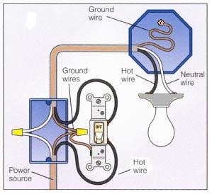
@ArnieX Here is the diagram of my light switch wiring: the light switch itself has 2 black wires and 1 copper(ground) connected. 2 white wires(neutral) are connected together. Do you think it will work? If yes, can you help me with the mapping between N, L, NO, NC and my wires ? |
|
Hi Alex, you are good to go. I would disconnect Ground wire from the switch as this is not needed when it is connected to low power part of swifitch. Then you need to connect neutral to N, black input to L (line), then black output wire to NC or NO this means Normaly Open or Close. Close is that when there is no power to relay it is ON, when you choose Normaly Open it means that the connected appliance is OFF when there is no power to relay. Than programatically you change the default state by applying power to relay. Just pick one, try how it works for you and you could change that later. My recommendation is to start with NO. Then you need to replace those black wires with low voltage ones and connect swifitch to switch pin D2 and GND. Make sure no high voltage cables are connected to the switch anymore. If you are unsure I’m not electrician and I do not know US standards so if not sure let someone to check if you have it wired correctly. Please do not get yourself killed. Let me know how it went. It should be pretty straightforward. So N (white), L (black input comming from bottom), NO (black going to light). Make sure that white wire go to swifitch and still continue to light, it won’t work otherwise. |
|
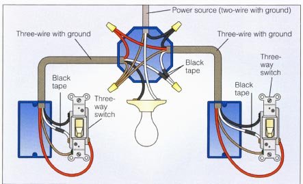
This is always the hardest scenario ;). You basically need to install ONE swifitch that will actually toggle the light. In the other switch you will need to sacrifice one swifitch to not do anything else other than sending command that switch was flipped. Then the other swifitch will toggle relay, this logic is better to do in Node RED than directly in swifitches. For the "dumb" swifitch you do not need to solder relay, diode and transistor at all and save it for other swifitch. Share some video when you have it working ;). |
|
Thanks! I will |
|
Hi @LubergAlexander, how is your project going? BR, Martin |
|
3 more components left to solder, ordered incorrect voltage regulators and
fuses. It is in progress - I will reply after I am done with pictures and
will probably have updates for the software.
…On Tue, Jan 23, 2018 at 12:34 PM, Martin Doubek ***@***.***> wrote:
Hi @LubergAlexander <https://github.com/lubergalexander>,
how is your project going?
BR,
Martin
—
You are receiving this because you were mentioned.
Reply to this email directly, view it on GitHub
<#6 (comment)>, or mute
the thread
<https://github.com/notifications/unsubscribe-auth/AA7HevwZw3fnKIEWXtwU6CkeMJoTDM6fks5tNkI3gaJpZM4Q8jCf>
.
|
|
Yeah that can happen ;). Otherwise awesome. Looking forward for the code updates. I'm open to any improvements. |
|
@ArnieX I will get back to you on that, but while I am still building the first one, here are a few improvements I would like to make:
|
|
Sounds interesting. 1, I can't imagine usecase for this, but may have some for some people. How about just adding topic to disable/enable analog switch? That would maybe do this easier. Instead of asking for permission on demand, it will already know if it has it or not. 2, Good luck ;). I don't think it's necessary for local setup but may be good for remote locations. 3, Hmm ;) this sounds like I still got lot to learn :D, but unit tests could be good to have thought. |
|
@ArnieX quick update - finally tried to connect it - worked the first try! Toggled the lights with MQTT commands. I will do some cleanup, want to embed a couple boxes behind existing switches and then will post a connection diagram and pics! |
|
Well done! Congratulation ;). Looking forward. |


Hi,
First of all, huge thanks for this awesome project!
I would like to try to install it behind existing light switches and rewire them so I can reuse the actual physical switch to control the lights + have the ability to do it remotely.
It looks like the main component which would depend on the mains voltage is the Hi-Link HLK-PM01, and it seems that its compatible with both 220 and 110V. Do you know about any other components which may be affected? Can it be used in the US?
Second question is regarding the physical switch. I read the firmware source code, and it looks like I can connect the 'analog' switch to D4... Have you tried to use it in a similar setup? I want to have both a physical switch + remote control.
if the previous question is indeed possible, can you please explain how to wire it? I think it will be beneficial to add to Readme as well. (How to connect the existing switch to D4 so it acts as a button + connecting the mains to swifitch)
The text was updated successfully, but these errors were encountered: