David's Pretty Satisfactory Gps-disciplined Oscillator
Accurate frequency reference for measurement equipment.
A 10MHz OCXO is tuned to a timing signal of a GPS, e.g. the 1PPS output. A frequency syntheziser then generates different signals from this reference as needed/configured by the user.
Currently I am working on the firmware for V1 of the PCB. During that I found multiple issues with PCB-V1 (Schematic) which hopefully culminate in another revision of the PCB, and then the firmware. See PCB-V1 ERRATA.
I.e.: usable, but only as a prototype development platform for V2.
The main control loop (OCXO -> frequency comparison -> DAC) works and the OCXO can be tuned to the GPS signal within 1PPB or better.
The chosen tiny FPGA is too small to hold all the logic that was designated for it. Most LEDs are connected to it and cannot be addressed because of that. Currently also the rotary encoder and buttons are connected to it and are usable, but may be removed to have more logic for frequency adjustment. In PCB-V2 I will likely move the UI to the microcontroller, or pick a slightly larger FPGA, e.g. the HX1K.

OCXO: refurbished 8663-XS with 10MHz output
DAC: AD5761R 16bit high quality low speed DAC with internal reference, generates tuning signal for OCXO
GPS: uBlox NEO 7M module with 1PPS output
VCXO: Si5351-C frequency generator for programmable output frequencies
-
CLK0: 90MHz as input for frequency comparison in the FPGA (for automatic tuning)
-
CLK1: 10MHz reference output signal
-
other programmable outputs (currently disabled)
FPGA: Lattice LP384: measures difference between the generated reference output and the GPS reference signal. That information is used to calculate the tuning voltage for the OCXO.
uC: nRF52840 as system- and display-controller
Power input: 14-16V
PMIC: TPS652510 PMIC generating three rails of:
-
12V: OCXO
-
3.3V: digital logic
-
1.2V: FPGA core voltage
Additional LDO for:
- 10V: DAC output rail (from 12V rail)
Temperature sensors: MCP9808 under OCXO and on bottom-side of PMIC (not visible in photo).
User interface:
-
SSD1306
-
Rotary encoder and buttons (via FPGA)
-
LEDs (currently not addressalbe as FPGA cannot hold more logic)
Interfaces:
-
USB to both GPS receiver and microcontroller
-
potentially Bluetooth or 802.11.5 to microcontroller
-
JTAG/SWD to microcontroller
A list of some hobby GPSDO designs: https://attila.kinali.ch/blog/2016/02/07/gps-disciplined-oscillator
A GPSDO with rubidium standard: http://www.medpants.com/my-reeds/itemlist/category/28-electronics
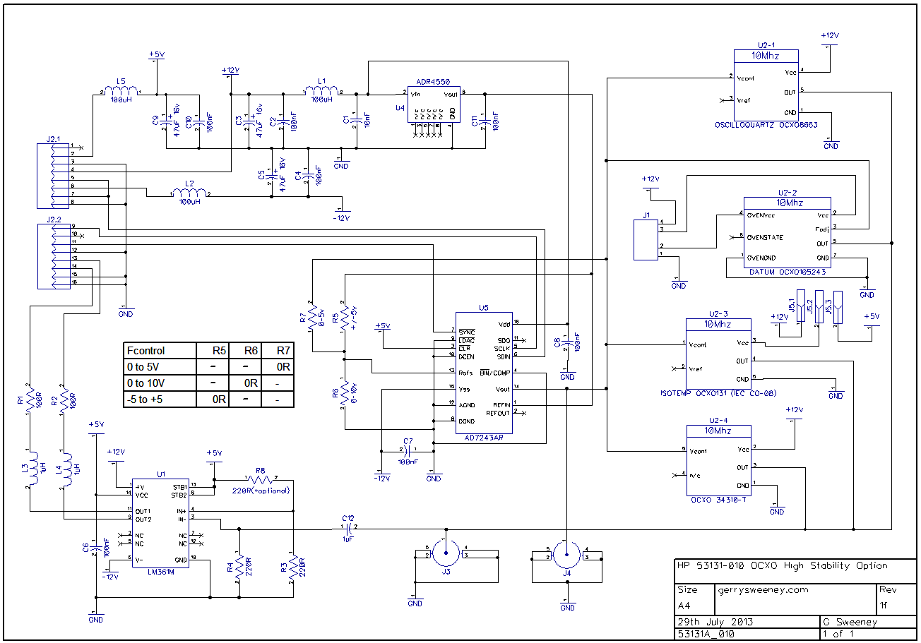
Alternative OCXO tuning schematic: https://gerrysweeney.com/wp-content/uploads/2013/10/OCXO-Rev-1F.png
"bt7tbl" GPSDO that can be bought on the internets: https://www.eevblog.com/forum/testgear/bg7tbl-gpsdo-master-reference/
Single-chip GPSDO control loop GPSDO: https://www.analog.com/media/en/technical-documentation/application-notes/AN-1002.pdf
"OpenPPS" GPSDO project: http://www.rocketmanrc.com/openpps.html
"Themis" GPSDO from HPSDR: http://openhpsdr.org/wiki/index.php?title=GPSTCXO
GPSDO by dfannin: https://github.com/dfannin/gpsdo