Errata and Workarounds
Add Jumper between AGND and DGND
- Connect the following points.

This modification increases the signal-to-noise ratio.
Remove Q14 then Jumper between Gate and Drain
- Remove Q14 , R49
- Solder the wire as follows.

Change the values
- R76 change from 560Ω to 1.2kΩ
- R74 change from 4.7kΩ to 100kΩ

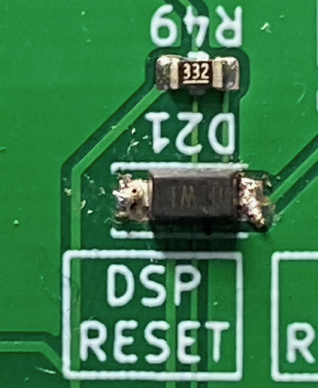
Add Capacitor on DSPRESET
- Connect the 10uF on SW2(DSP RESET BUTTON)

or mount the 10uF capacitor beside the D21 anode and the DGND plane.

-
Reverse the Diode D21
Temporary workaround for power-on DSP reset action.
-
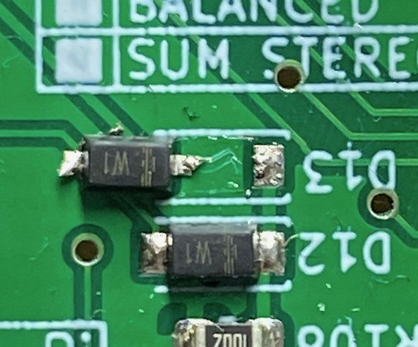
Remove the Diode D13
Misunderstand Amanero Combo384's MUTE polarity. (It was active-low)
-
C13 keep away from U3
To prevent the U3's heat ephemeral.
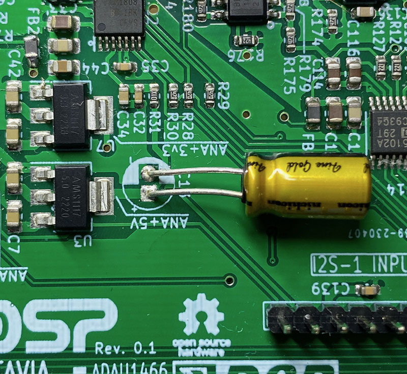
Nice to add a heatsink on U3/U7.

-
R7, R33 Change the Value to 3.3k ohms
Expand the working supply voltage range from 6.5V to 12V. If you use the power supply voltage less than 9V, you don't need to add a heatsink on the U3/U7.

-
R76 Change the value to 330R
To reduce the gain of the coaxial S/PDIF receiver amplifier.

-
Source Selector Position Indicator LED
The J13-pin1 Anode side net was connected to the raspberry-pi's power rail +5V, So the LED does not turn on during the Raspberry-pi is not active. If the LED is turned on, It's too bright to see from the front. The workaround is attached picture (Use the ADC J3 header's pin6 +3.3V instead of the current design)

-
Programming Parameter change for 256kbit M95256 EEPROM
The code-page size is different from the 25LC1024. So you need to change the "Memory Size" 262144, "Page Size" to 64, and the "N of Address Bytes" equals 2.
