rendering transformations
-
Motivation: Transform the entire dataset before rendering it to achieve both fun and profit
-
Contact: Andrea Aime
-
Tagline: Because transforming datasets is more powerful than transforming just geometries
Geometry transformations have been added almost one year ago to GeoTools to allow the application of a filter function to the geometry before rendering it. This allows for quite a bit of flexibility, yet still fails to address some needs:
- transformations that do need to take into account more than one feature at a time
- transformations that perform raster to vector transformations, like contouring
The recent evolutions in processing land suggest we can do these kind of transformations by bridging between the SLD world the the process/WPS world, allowing the user to invoke a process that would sit in between the data source and the rendering engine. The SLD style sheet is a neat place to do this as it allow for dynamic applications to be written that would just change the style on the fly to extract different views out of a given data set (for example, changing on the fly the contour levels to be extracted).
The first step is to take FeatureTypeStyle and add a transformation field which would specify a source to target transformation applied on the data:
public interface FeatureTypeStyle extends org.opengis.style.FeatureTypeStyle {

    /**
     * The eventual transformation to be applied before rendering the data (should be an expression
     * taking a feature collection or a grid coverage as the evaluation context and returns a
     * feature collection or a grid coverage as an output)
     * @return
     */
    Expression getTransformation();
}
The transformation would be feeded with the source data, either a FeatureCollection or a GridCoverage2D, and would return another set of data, agains as a FeatureCollection or a GridCoverage2D
Now, most of the meaningful rendering transformation can also be considered as valuable stand alone processes. It makes sense to bridge the two worlds so that SLD can call onto a process via the above transformation.
This is achieved by a filter/process bridge, a FunctionFactory called ProcessFunctionFactory which looks for all processes that will return just one result and that generates function wrappers around them. In fact, a function is just a process that returns a single output, and vice versa, any process returning a single output can be seen as a function.
There is however a mismatch to be solved, function arguments are positional, process arguments are named instead. The mismatch has been solved by making the process function wrappers access parameters that are maps from a string (the argument name) to a value, and creating a function, called "parameter" that builds those maps.
The "parameter" function will assume the first argument is always the parameter name, whilst the value of the returned map will be:
- its context (the feature collection or the coverage) if the argument is just one (which is assumed to be the process parameter name)
- the second argument if there are only two
- a List collecting all of the arguments besides the first if there are more than two
This takes care of all the normal needs, that is, passing the source dataset to the process, passing a given single valued argument, or passing down a multivalued argument.
This allows to build a transformation in SLD that looks as follows:
      <FeatureTypeStyle>
        <Transformation>
          <ogc:Function name="gs:Contour">
            <ogc:Function name="parameter">
              <ogc:Literal>data</ogc:Literal>
            </ogc:Function>
            <ogc:Function name="parameter">
              <ogc:Literal>levels</ogc:Literal>
              <ogc:Literal>1100</ogc:Literal>
              <ogc:Literal>1200</ogc:Literal>
              <ogc:Literal>1300</ogc:Literal>
              <ogc:Literal>1400</ogc:Literal>
              <ogc:Literal>1500</ogc:Literal>
              <ogc:Literal>1600</ogc:Literal>
              <ogc:Literal>1700</ogc:Literal>
              <ogc:Literal>1800</ogc:Literal>
            </ogc:Function>
          </ogc:Function>
        </Transformation>
        <Rule>
...One of the major performance points in a rendering chain is reading only the data strictly needed to paint the current request. Rendering transformations can alter the current query/raster read area significantly, if so, it should implement the following interface:
/**
 * An interface to be implemented by processes or by filter functions meant to be integrated as
 * feature collection/grid coverage transformations in a rendering chain.
 * <p>
 * These functions are meant to take one layer (raster or vector) and apply transformations on top
 * of it
 * <p>
 * The method provide information about how the data is altered so that the renderer can query the
 * appropriate part of the input data that will feed the process/function
 * </p>
 *
 * @author Andrea Aime - GeoSolutions
 */
public interface RenderingTransformation extends Function {

    /**
     * Given a target query and a target grid geometry returns the query to be used to read the
     * input data of the function This method will be called only if the input data is a feature
     * collection.
     *
     * @param targetQuery
     * @param gridGeometry
     * @return The transformed query, or null if no inversion is possible/meaningful
     */
    Query invertQuery(Query targetQuery, GridGeometry gridGeometry);

    /**
     * Given a target query and a target grid geometry returns the grid geometry to be used to read
     * the input data of the function involved in rendering. This method will be called only if the
     * input data is a grid coverage or a grid coverage reader
     *
     * @param targetQuery
     * @param gridGeometry
     * @return The transformed query, or null if no inversion is possible/meaningful
     */
    GridGeometry invertGridGeometry(Query targetQuery, GridGeometry targetGridGeometry);
}
Processes wishing to participate in the rendering will implement a similar one, which will be adapted to the above one by the filter/process bridge:
/**
 * An interface to be implemented by processes meant to be integrated as feature collection/grid
 * coverage transformations in a rendering chain.
 * <p>
 * The method provide information about how the data is altered so that the renderer can query the
 * appropriate part of the input data that will feed the process
 * </p>
 *
 * @author Andrea Aime - GeoSolutions
 */
public interface RenderingProcess extends Process {

    /**
     * Given a target query and a target grid geometry returns the query to be used to read the
     * input data of the process involved in rendering. This method will be called only if the input
     * data is a feature collection.
     *
     * @param targetQuery
     * @param gridGeometry
     * @return The transformed query, or null if no inversion is possible/meaningful
     */
    Query invertQuery(Map<String, Object> input, Query targetQuery, GridGeometry gridGeometry);

    /**
     * Given a target query and a target grid geometry returns the grid geometry to be used to read
     * the input data of the process involved in rendering. This method will be called only if the
     * input data is a grid coverage or a grid coverage reader
     *
     * @param targetQuery
     * @param gridGeometry
     * @return The transformed query, or null if no inversion is possible/meaningful
     */
    GridGeometry invertGridGeometry(Map<String, Object> input, Query targetQuery,
            GridGeometry targetGridGeometry);
}
In case the above support is not available the original data will be read in any case within the limits of the current rendering request and at its resolution.
Me, Simone and Michael worked together in GeoServer and jaitools to setup transformation that would extract contour lines, polygons surrounding cells withing a certain data range, single pixels as points to allow rendering coverages as vector data sets instead.
The processes are still being worked on and will eventually be backported to GeoTools (we still need to figure out how to best organize the processes into GeoTools plugin modules, as well as moving the process module to supported status, that will require more work and time).
Here are some examples of the rendering transformations we're currently working on.
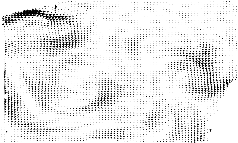
In this case we have a raster layer with two float64 bands containing the u and v components or a wind vector. The style first extracts the pixel centers as a list of points whose attributes are u and v, then composes them to generate magnitude and direction of the wind arrow, finally it activates conflict resolution so that no two arrows overlap with each other.
The following map shows a zoomed out result (click on the image to see it full size):

and here is a detail of the same map:
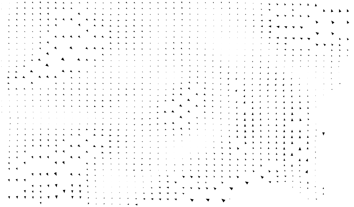
Conflict resolution is optional (and actually takes a toll performance wise), here is a screenshot without conflict resolution enabled:

The SLD generating the first two maps is attached as garrows.sld, the one for the last map is garrows2.sld
See how the <Transformation> tag invokes the raster -> points transformation, and how the magnitude and direction of the vector are computed outside of the two u/v components (band1 and band2 respectively in the raster)
In this case the transformation extracts contours out of a DEM at user specified levels and then paints them labeling them according to their elevation.
Here is the result:

The above map is still affected by tile border effects which occasionally break the contour lines (the source DEM is inner tiled) Zooming in we also used the pixel to point transformation to label each pixel with its altitude, providing a label with the pixel value:
![]()
The style used to generate the contours has been attached as gcontour.sld whilst the one that extracts each single pixel value is gpoints.sld
In this case the transformation extracts the polygons of all the cells between 1300 and 1500m, and a second range between 1700 and 1900m. The polygons are then colored according to the range they are associated to, red for the first, green for the second. The result looks as follows:

Zooming in we can see the polygon extraction working against cell borders:

While this may look ugly it's accurate and geometrically correct: trying to smooth the polygons would likely generate either polygon overlaps or gaps between the polygons (especially visible in case of compact set of subsequent ranges), if not invalid geometries (as in having hole rings intersecting the outer hulls).
The style used to generate this map has been attached as gpolygons.sld
The work is of medium size, requires one API addition to the FeatureTypeStyle interface that has a single implementation (and low likeliness that anybody else implements it).
Besides that it requires changes in the SLD parser and in the streaming renderer to apply the transformations.
Most of the changes are out of the way of the main code paths so we're aiming at having this available on the new 2.7.x stable branch. However since GeoServer is already in RC state we'd like to postpone these commits to a time after the release of GeoServer 2.1.0 (provided that does not delay too much) to avoid any cause of instability.
If needed we can commit just the API changes before the rest of the changes so that no API breaks happen after GeoTools 2.7.0-RC1
This proposal was accepted and is present in the 2.7.x series.
Voting has not started yet:
- Andrea Aime +1
- Ben Caradoc-Davies
- Christian Mueller +1
- Ian Turton +1
- Justin Deoliveira +1
- Jody Garnett +1
- Michael Bedward +1
- Simone Giannecchini +0
The only API change is the addition of a method in FeatureTypeStyle as described above
We plan to document this as the geometry transformations as part of the GeoServer documentation. The GeoTools documentation can link to it, and eventually we can add an example of setting up a transformation in code once the GeoServer processes have been back ported to GeoTools.