Getting started with 32F769IDISCOVERY
I went to:
- https://www.st.com/en/evaluation-tools/32f769idiscovery.html clicked on "Direct order" and ordered "32F769IDISCOVERY Discovery kit"
- it was dispatched from Mouser and delivered by FedEx overseas
- I'm looking forward to play with color LCD touche display, Codec, SD card, USB and all other funny stuff - but maybe there is too much fun ....
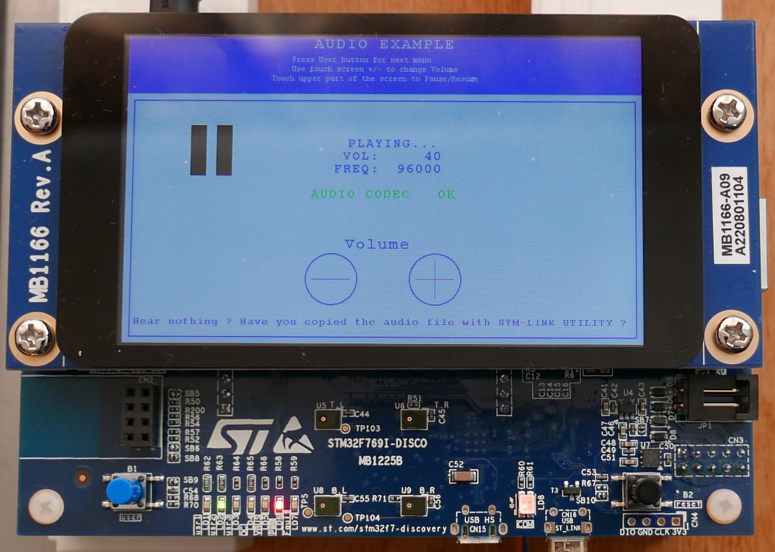
Here is board with LCD display running BSP Example at Audio demo stage:
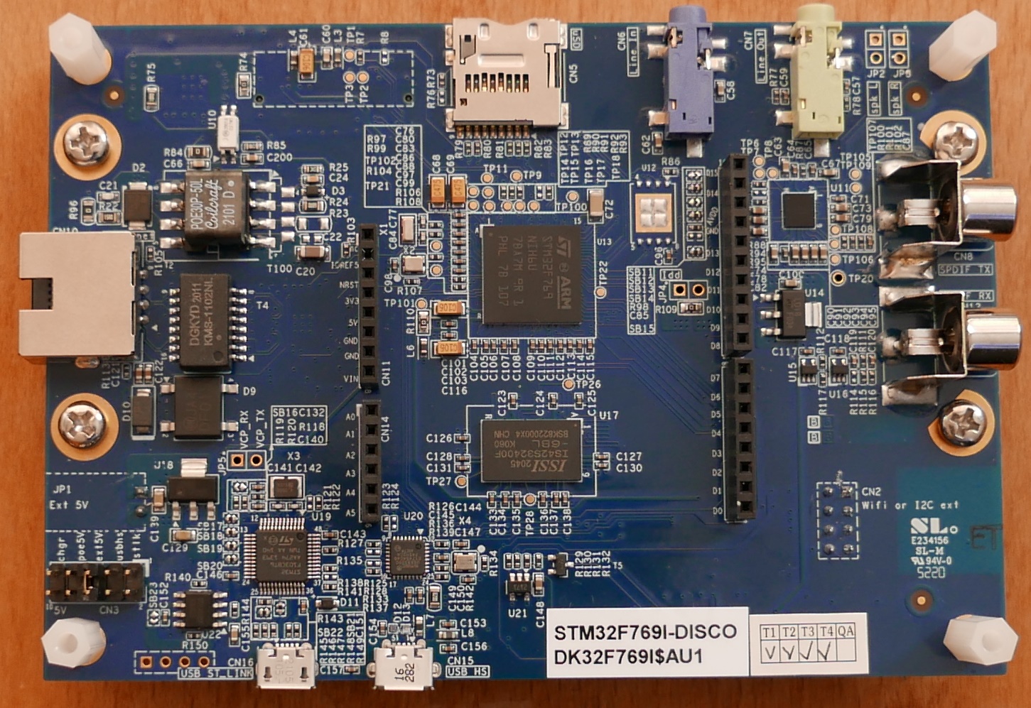
And bottom of board (disconnected) or maybe top - depends on your world view:
Required additional accessories:
- USB A to Micro-B to program board
Before connecting board download manual from:
- homepage: https://www.st.com/en/evaluation-tools/32f769idiscovery.html
- manual link: https://www.st.com/resource/en/user_manual/um2033-discovery-kit-with-stm32f769ni-mcu-stmicroelectronics.pdf
- carefully study chapter
5.4 Power supplyand decide which EXTERNAL power supply (not usb) you will use.
Identifying board revisions:
-
at first there is sticker with "Product identification" (again see UM2033 for details). In my case it is
DK32F769I$AU1which is described in manual as:- MCU:
STM32F769NIH6 revision Z or 1, actually:STM32F769NIH6U - Errata:
ES0334 - Boards:
-
MB1225-F769I-B03(main board) -
MB1166-DEFAULT-A09(LCD daughterboard)
-
- MCU:
-
in case of display it is easy - there is sticker on top. In my case
MB1166-A09which means Display board revision A09 (see next chapter for important notes) -
in case of mainboard it is more difficult because revision sticker is right under bottom of display. In my case it is
MB1225 F769I-B03 -
please read carefully
um2033-discovery-kit-with-stm32f769ni-mcu-stmicroelectronics.pdfwhere are following notes (chapter 8.3 Board revision history)- mainboard: Memory
MICRON MT48LC4M32B2B5-6A IT:LTRreplaced byISSI IS42S32400F-6BL - display: LCD
FRIDA FRD400B25025-A-CTKis replaced byFRIDA FRD400B25021-B-CTQ
- mainboard: Memory
WARNING! I was unable to find that display on https://en.fridalcd.com/ because it seems that there are actually 2 things combined: TFT LCD display + Touch overlay (???)
- controller? But here are at least some pointers (click on your own risk!):
- NT35510 datasheet: https://focuslcds.com/content/NT35510.pdf
- NT35510 wiki: http://www.lcdwiki.com/3.97inch_16BIT_Module_NT35510_SKU:MRB3973
If your display is Rev A9 - sticker MB1166-A09 on display there are
important issues you have to solve:
Original STM32CubeF7 applications will not work properly unless Program Code that is correctly modified for MB1166-A09 display!
Following modifications are required:
- You must use firmware
STM32Cube_FW_F7_V1.17.1or later:- go to page: https://www.st.com/en/embedded-software/stm32cubef7.html
- and download both
en.stm32cubef7_v1-17-0.zipanden.stm32cubef7-v1-17-1.zipand unpack them in that order overwriting older files...
- Remove or un-define macro
USE_STM32F769I_DISCO- IMPORTANT! - Enable preprocessor macro
USE_STM32F769I_DISCO_REVB03 - If your code directly calls OTM8001A_init() Following initialization change is required:
// comment out line below
//   OTM8009A_Init(OTM8009A_COLMOD_RGB888, LCD_ORIENTATION_LANDSCAPE);
// add this line instead:
NT35510_Init(NT35510_FORMAT_RGB888, LCD_ORIENTATION_LANDSCAPE);
WARNING!
Replacing
OTM8009A_Init()is NOT enough! There are also important changes regarding GPIO port settings - which has significant impact on board consumption!Best way is to follow for example
STM32Cube_FW_F7_V1.17.0\Projects\STM32F769I-Discovery\Examples\BSP\Src\main.cand rather call just:/* Initialize the LCD */ lcd_status = BSP_LCD_Init(); while(lcd_status != LCD_OK);Instead of duplicating low level initialization.
If you still insist on using Low-level initialization look at
STM32Cube_FW_F7_V1.17.0\Drivers\BSP\STM32F769I-Discovery\stm32f769i_discovery_lcd.ccode around "ifdefs" withUSE_STM32F769I_DISCO_REVB03macro...
Resources:
- https://community.st.com/t5/stm32-mcus-touch-gfx-and-gui/stm32f769i-disco-really-noisy-tft-lcd-display/td-p/55127
- https://community.st.com/t5/stm32-mcus-products/lcd-mb1166-a09-and-lcd-mb1166-a03/td-p/574834
- https://github.com/STMicroelectronics/STM32CubeF7/commit/6eed5bb15304480bbd7cde7a30208d579fbde9dc#diff-7f4e9ae42bf83eb3d8371345a2edafd6345f79f2d658eb863382f01c8a8f8ed4
- https://community.st.com/t5/stm32-mcus-touch-gfx-and-gui/stm32f469-discovery-looking-for-working-example-cubemx-touchgfx/td-p/199739
That was easy, but...
However there was second problem:
- after few minutes there are apparent several defects
- right 2/3 of display are darker than left 1/3
- even later display starts flickering and there are noticeable problems (garbage etc...)
- and even later it is blended and it looks like entry in tunnel
- RESET does not help - only power off for some time and power on again...
Possible cause:
- Incorrect GPIO initialization that causes board to draw excessive current
- or general overheat issue, but...
- I have found that while some demos have issues tha display started
break down, but others (for example
STM32Cube_FW_F7_V1.17.0\Projects\STM32F769I-Discovery\Examples\BSP) works well even for hours while powevred just via ST-LINK
Potential problem:
- complete display inlucding backlight is connected to PIN36 of CN1 which is connected to 3V3 (see mb1166-default-a10-schematic.pdf and mb1225-f769i-b03_schematic.pdf)
- but 3V3 depends on U7 LD39050PU33R (see https://www.st.com/resource/en/datasheet/ld39050.pdf the suffix "PU33" is saying that output voltage is fixed 3.3V, max current 500mA if temperature is below limit) that converts 5V to 3.3V for nearly all board except ST-LINK.
-
Pd = (Vin-Vout)*Iout = (5-3.3)*IoutsoPd = 1.7 * Iout. On PSU typical current was around 350mA to 380mA, so Pd around 0.6W - It is not easy to estimate maximum allowed power. But we can use finger. U7 can be find on "display side" - small rectanble between RESET button and CN3
- similar problem is in case of U18 LD1117S50TR used to convert VIN (7 to 12V) to 5V.
(Again S50 means fixed voltage 5.0V, and Imax=800mA but again depends on temp)
I used 8.1V for VIN and saw current 0.4A which means:
Pd = (Vin-Vout)*Iout = (8.1-5)*Iout = 3.1Iout. For Iout=0.4A we get Pd=1.24W U18 can be find on bottom side (where is CPU) nearby JP1. It is easy to find because it has only 4 pins and 4th pin is really wide to improve cooling.
Outcome:
- so I have to watch temperature of U7 when using 5V power source
- and additionally I have to watch U18's temperature when using VIN. However U18 has at least thick colling pin.
- both U7 and U18 are linear regulators (so very low noise and perfect transient reaction, but higher power dissipation than most DC/DC converters)
- please note that too high current consumption can be also casued for wrong software (when some GPIO pins are configured incorrectly etc) - to it is another thing to be watched.
There is nice BSP demo that does not require additional accessories and shows most interesting hardware features including touch display, audio codec, SD card and other components tests.
Required software:
- STM32CubeProg tested v2.14.0 needed to store example audio data to Flash (IDE is able to store program only into flash)
- STM32CubeIDE tested v1.13.2
-
STM32CubeF7 you need to download both
main archive
en.stm32cubef7_v1-17-0.zipanden.stm32cubef7-v1-17-1.zip. Unpack these archives into same (!) directory in specified order - the patch archive will overwrite few existing files. I use pathc:\Ac6\STM32Cube_FW_F7_V1.17.0
How to build:
- we will use this example
c:\Ac6\STM32Cube_FW_F7_V1.17.0\Projects\STM32F769I-Discovery\Examples\BSP\SW4STM32\STM32769I-Discovery - if you have LCD display A09 revision you need to fix change macro.
- open file
.cproject(from above location) in Text editor - change line:
<listOptionValue builtIn="false" value="USE_STM32F769I_DISCO"/> - to:
<listOptionValue builtIn="false" value="USE_STM32F769I_DISCO_REVB03"/> - now we can import this project to STM32CubeIDE
- run STM32CubeIDE
- click on Import ... -> General -> Import ac6 System Workbench for STM32 Project
- select directory
c:\Ac6\STM32Cube_FW_F7_V1.17.0\Projects\STM32F769I-Discovery\Examples\BSP\SW4STM32\STM32769I-Discovery(directory where are.projectand.cprojectEclipse file. - confirm Upgrade (original project are for previous IDE SW4STM32)
- now right-click on project and select
Build Project - ignore Warnings about
close()...that are presented as error, however required .elf file is build anyway. - now right-click on project and select Run As ... -> STM32 C/C++ Application
- Program target device
However to play audio sample we need to store it first to Flash memory:
- Run programmer IDE: STM32CubeProg
- select Download tab
- select file
c:\Ac6\STM32Cube_FW_F7_V1.17.0\Projects\STM32F769I-Discovery\Examples\BSP\Binary\audio_sample_tdm.bin - manually fill start address from readme.txt
0x08080000 - and click Start Programming
- After programming push RESET button
Now watch display and follow instructions...
Does not work yet - I have no right USB cable
Requires additional accessories to proceed beynd logo:
- USB penddrive for multi-media files (not sure about supported filesystem)
- USB micro A-Male to A-Female cable - required to connected USB pendrive directly to board
- Download and install STM32CubeProg from: https://www.st.com/en/development-tools/stm32cubeprog.html Tested version 2.14.0
- Download and unpack somewhere ZIP with demo - tested url: https://www.st.com/content/ccc/resource/technical/binary_resources/compiled_demos/group0/73/8c/7f/19/ad/dd/42/e6/32F769IDISCOVERY_Demo/files/32F769IDISCOVERY_Demo.zip/jcr:content/translations/en.32F769IDISCOVERY_Demo.zip
Now:
- Ensure that your board is properly powered - recommended Power supply (tested VIN, lab PSU 8V, 1A) - but not sure if it is really required or demo is just using wrong GPIO init code...
- Connect your board to PC
- Run STM32cubeProg
- Now click on
Connect - Ensure that ST-LINK was properly detected
- You may be prompted that you have to upgrade ST-LINK firmware. Answer yes and follow instructions
- Before programming demo you have to enable "External Loader"
Click on
ELicon on the left and selectMX25L512G_STM32F769I-DISCO - Before goind any furhter ensure that on right window "ST-LINK configuration" there is line "External loader: MX25L512G_STM32F769I-DISCO". It must be there otherwise external Flash will be skipped and not programmed at all
- now select tab "Download" (Download button)
- and open in
File pathfile32F769IDISCOVERY_demo\Binary\STM32769I-DISCO_DEMO_V1.0.0_FULL.hex - Check
Verify after programmingand checkRun afte programming - Finally click on
Start programming - Please be patient - it may easily take around 10-20 minutes...
Please note that all existing (non-RTOS) LCD Exmples are not compatible with CubeMX as can be seen under CubeMX -> New Project -> Example Selector below:
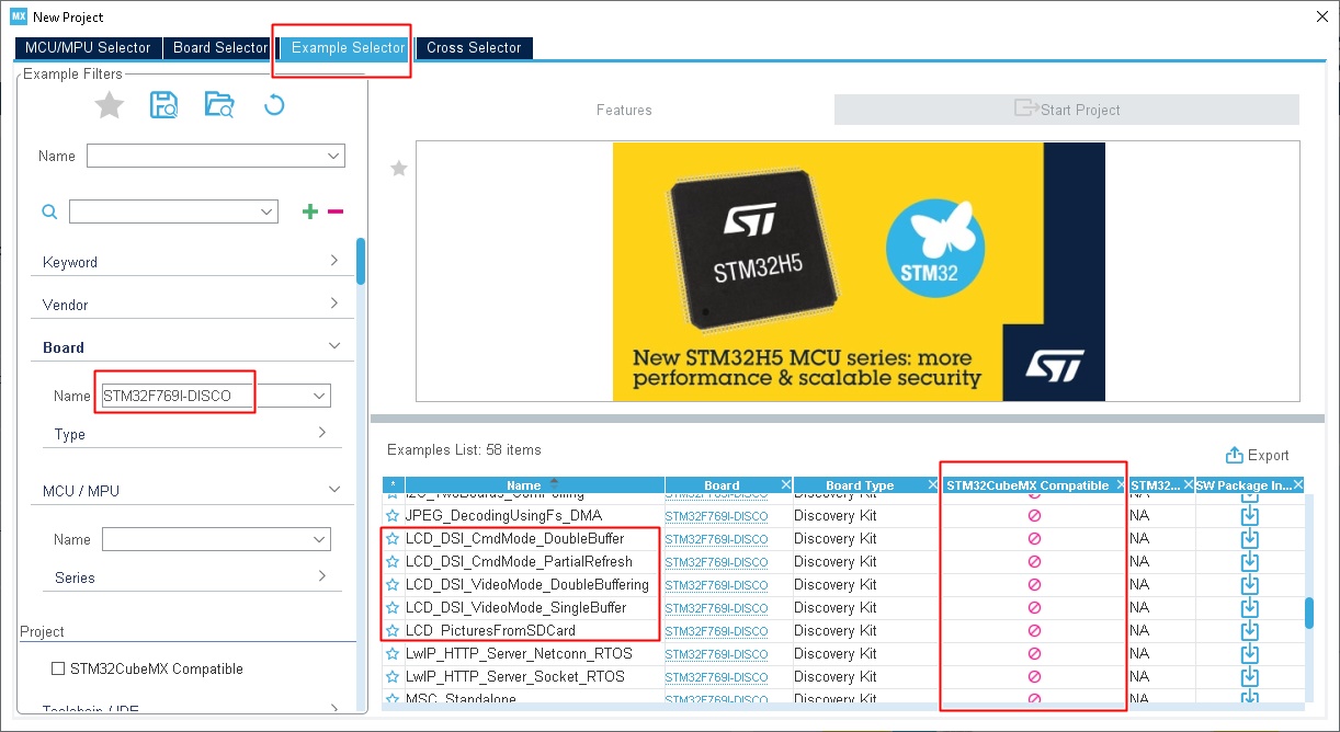
And here is list of all CubeMX compatible examples for Discovery board:
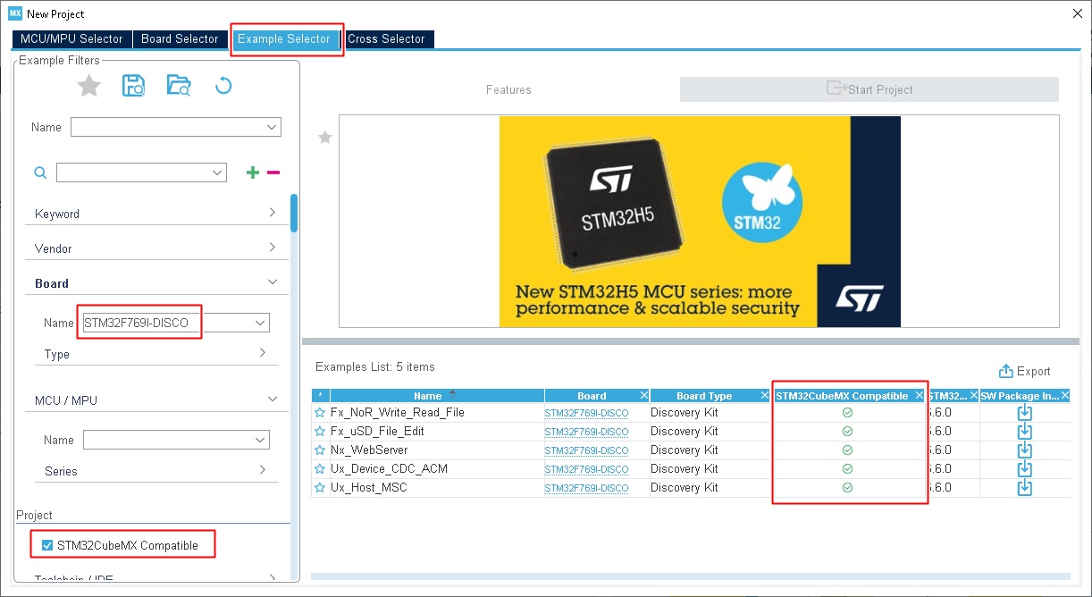
Please note that all compatible examples use X-CUBE-AZRTOS RTOS package.
So for LCD we have tough choice:
- adapting BSP examples, but doing all future changes and peripheral addition manually without CubeMX
- use CubeMX but have to duplicate part or most of BSP code - which is generally challening but still possible
Not sure what is better...
Copyright © Henryk Paluch. All rights reserved.
