Reactor Zero
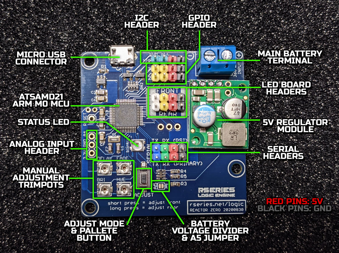
Original Logic Engine kits used two separate "AVR Boards" to control the blinkies. This was later superceded by the "Teensy Reactor" which used the much more powerful Teensy 3.2 to run both front and rear logics. More recent kits have included the "Reactor Zero" board which is based on the Arduino Zero.
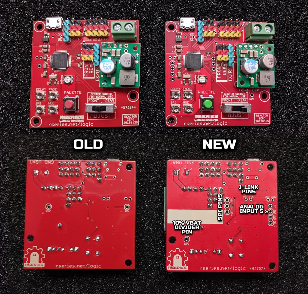
A second set of Serial headers was added, with voltage dividers on each RX pin to make them 5V/3.3V safe without an additional adapter. The Front & Rear headers were changed from 3-pin to 4-pin headers to allow for the new 4-pin 112 LED rear LED board. The I2C pins (SDA and SCL) now have some level shifting mosfets so 5V devices can be used without an adapter. The "Adjust Front/Rear" switch was removed.
You can find my basic Arduino sketches for the Reactor Zero board here.
For more advanced functions, the latest version of the Firmware by TheJugg1er can be found here: nhutchison/LogicEngine
To enter Adjustment mode using the V4/V5 Reactor Zero, slide the 'Adjust' switch from its center position to either the 'Front' or 'Rear' position.
With the V6 Reactor Zero, press the 'Adjust' button briefly to enter Front adjustment mode. Hold the button for a few seconds to enter Rear adjustment mode.
The Status LED will blink blue/white when adjusting the Front logics, or blink green/orange when adjusting the Rear.
To save settings, on the V4/V5 Reactor Zero board return the Adjust switch to center. On the V6 Reactor Zero board holding the Adjust button for a few seconds will save the current settings.
The Status LED will blink purple twice to indicate current settings have been saved, then go back to normal operation (slowly alternating between red and blue).
To 'factory reset' settings, hold the button for 10 seconds and release. The status LED will blink purple 6 times, and you should see the logics return to their standard settings.
Each press of the palette button will advance the palette by one color set. There are a total of six sets currently available, but more can be added easily.
Each color palette can be further adjusted by turning the HUE trimpot on the board using a small screwdriver. Turning the trimpot will shift all key colors of the palette up or down the color spectrum.
The Brightness can be changed using the BRI Pot on the board. Turning Clockwise will increase brightness, anti-clockwise will decrease brightness.
The DELAY and FADE trimpots can be adjusted to control the pattern speeds. DELAY will change the length of time that each LED stays at each key color. FADE controls how fast we fade between one key color and the next.
The Reactor Zero will listen for Jawalite commands coming in over the serial port. These could come from a Marcduino, and Arduino, or other microcontroller in your droid.
Note that since the Reactor Zero is a 3.3V device, any incoming signals (such as serial signals coming into the RX pin) should be around 3.3V to be on the safe side. If connecting to a 5V device (such as a Marcduino or PSI Pro) that 5V signal should be cut down to something that the Reactor Zero is happy with. The V6 Reactor Zero has a voltage divider built-in that reduces incoming voltage to the RX pin. For V4/V5 Reactor Zero boards, a separate voltage divider is recommended.
Neil's firmware also supports an additional serial port, intended for use with Maxstang's excellent PSI Pro's. This serial port is labeled on the V6 board as (PSI).
My firmware doesn't support any I2C communication. If you need I2C, have a look at Neil's firmware.
To allow for the droid's main battery level to be displayed on the logic displays, I added a voltage divider on the Reactor Zero. This takes the voltage from the screw terminal and uses two resistors to divide it down to 10%. At this level the voltage can be safely read by the microcontroller, so with appropriate firmware in place we can display battery level when commanded. A slight modification is needed to allow this.
V4/V5 Reactor Zero : On the back of the board you will see a thru-hole labeled "DIV" and another labeled "A5". With your battery connected to the screw terminal, use a multimeter to check DC voltage between DIV and one of the GND pins. It should read approximately 10% of the voltage that you're providing to the screw terminal (so if you've connected a 12V battery, DIV should read about 1.2V). Power off and place a short length of insulated wire connecting DIV and A5, soldering each end in place. Now our firmware will be able to safely read the voltage when it does an AnalogRead on the A5 pin!
V6 Reactor Zero : On the front of the board, to the right of the Adjust button, you should see solder-jumper pads labeled A5 on one pad and JP1 on the other pad. With your battery connected to the screw terminal, use a multimeter to check DC voltage between the JP1 pad and one of the black GND pins. It should read approximately 10% of the voltage that you're providing to the screw terminal (so if you've connected a 12V battery, DIV should read about 1.2V). Power off and carefully solder across both pads; this connects that 10% battery voltage to our A5 pin. Now our firmware will be able to safely read the voltage when it does an AnalogRead on the A5 pin!