Teensy Reactor
For basic logic functionality, simply...
- Connect the front LED boards to the Front pin header.
- Connect the rear LED board to the Rear pin header.
- Connect your power source (your droid's main battery) to the Power In screw terminal.
- The LED boards will now blink their blinky magic.
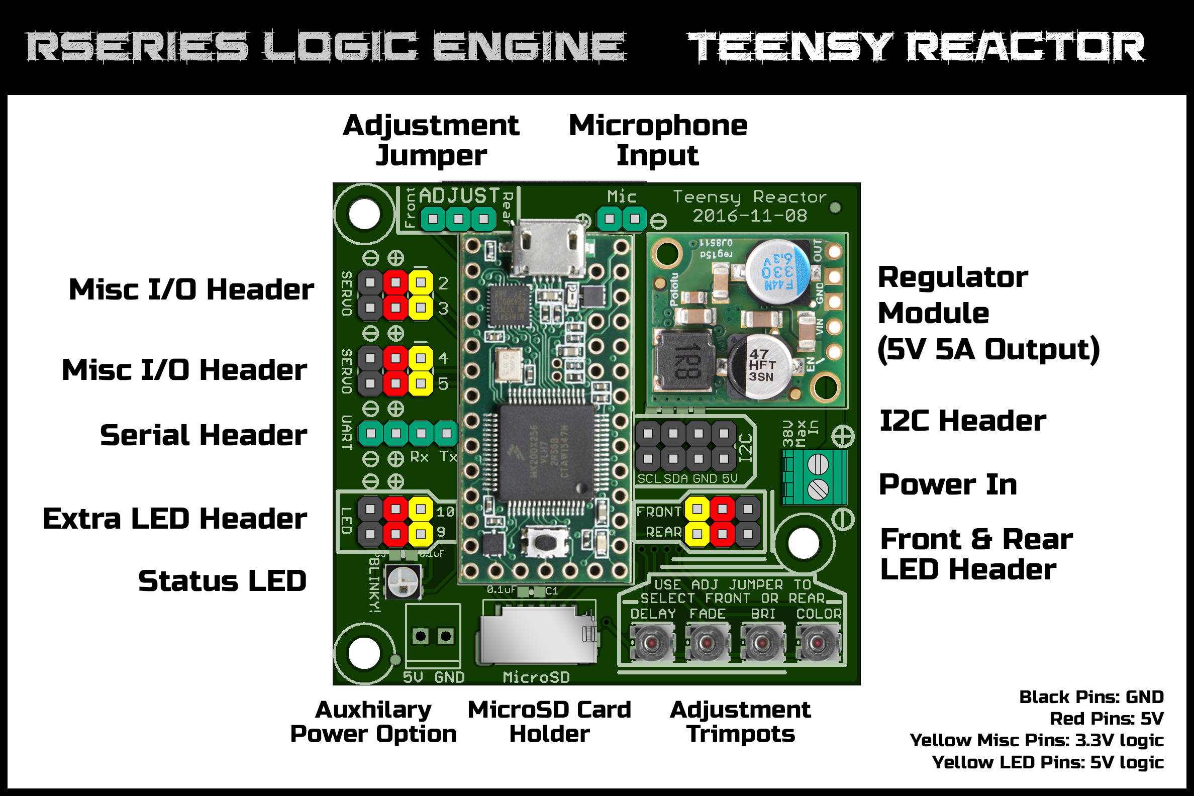
#Adjusting Logic Patterns To adjust the default color, brightness and speeds of the logic patterns, place a jumper/shunt on the Adjust header at the top of the Teensy Reactor to select either Front or Rear. Once the jumper is placed, the four Adjustment Trimpots at the bottom of the board will directly control the settings of the selected logic (front or rear). Use a small screwdriver to carefully turn these trimpots to adjust settings.
- DELAY : This adjusts the pause time of each LED when it reaches a key color.
- FADE : This adjusts the pause time of each LED as it is cycling though 'tween' colors.
- BRI : This adjusts the overall brightness of the logic (clockwise = brighter).
- COLOR : This shifts the color hue of the current color palette through the color spectrum.
Adjust the settings as you see fit, then remove the jumper to save the current settings to memory. These settings are saved to EEPROM memory, and will remain even after power is cycled.
The Teensy Reactor will listen for Jawalite serial commands coming from a Marcduino, Arduino, JEDI Controller or anything that can talk basic TTL Serial/UART at the JEDI standard speed of 2400 bauds.
Connect appropriate TX pin of your board to the RX pin of the Teensy Reactor's Serial/UART pin header. The boards should also share a common ground, so connect a GND to the (-) pin of Serial/UART pin header also.
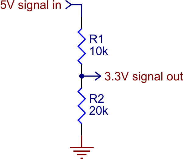
For the Reactor Zero, please note that the microcontroller requires 3.3V logic levels. This means that connecting a Serial TX from a 5V device such as a Marcduino or Arduino Mega to the Reactor Zero's RX pin could cause damage to the board. In cases like this, a simple two resistor voltage divider is recommended (where R2 is roughly twice the resistance value of R1).