Older Versions (pre 2016)
#Assembly (0) Overview
The circuit boards come fully assembled, but you'll need to spend a little time putting them together with the fiber optics before they're ready to be installed in your dome. Assembly is simple, but can take a little time so set an evening aside to get everything together. The general procedure is...
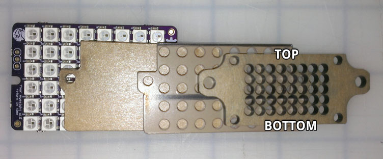
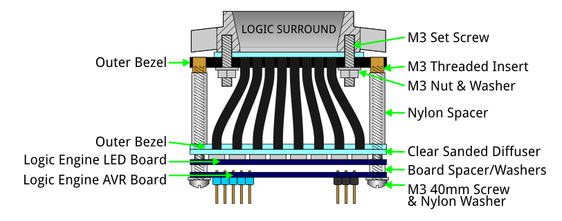
- Inner screen, inner bezel and outer bezel are attached to the LED boards using screws and spacers.
- Fiber-optic cable is threaded through the outer bezel and into the inner bezel so it points directly at an LED.
- Once positioned the fiber-optic cable is trimmed to size at the outer bezel.
! Never connect or disconnect LED boards from the AVR boards while powered; doing so can kill LEDs!
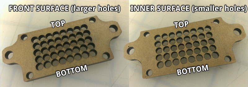
! The plastic bezels are laser-cut and holes have a slight taper. This results in the openings of the "fiber holes" being slightly larger in diameter on one side. When assembling the bezels & screens these larger openings should face outward to make inserting the fiber-optic cable simpler.
! Mounting the AVR board to the back of an LED board can create a short if not done carefully. To be safe, trim down the back of the soldered Teeces pins so they're almost flush with the PCB surface, then cover them with a small piece of electrical tape. You may want to do the same with the OUT pins of the LED boards as an extra precaution.
##Changes to Kits ###June 2015 Kits The June 2015 Kits are almost identical to the Sept 2014 ones. Instead of a 16mm screw there's now a 20mm screw, and an extra nut and washer. The longer screw together with a washer and nut hold the Rear inner bezel to the inner screen, preventing the plastic from bowing out during assembly. Front LED PCB's and now a hair smaller to make mounting in the dome easier (boards are less likely to bump into each other). ###September 2014 Kits The plastics and hardware of the newer kits were changed slightly to simplify assembly. Rear LED PCB is now a single board rather than two PCBs soldered together. Front LED boards now have 40 LEDs; the unused top/bottom row of 8 LEDs has been removed.
Below is the Sept 2014 Assembly Video, which is also very relevant to the current kits...

#Assembly (1) Front
##Front Master This is the upper front logic and connects directly to the AVR Board. The LED board has two sets of 3 pins; one set labeled IN and another labeled OUT. We piggyback the AVR Board directly to the back of the LED board using those IN pins.
Parts & Hardware Required:
- (1) AVR board (the one without the yellow jumper)
- (1) Front LED board (the one with side "OUT" pins)
- (1) Front Inner Screen (to be lightly sanded)
- (1) Front Inner Bezel
- (1) Front Outer Bezel
- (2) 40mm M3 screws
- (2) 3/4" spacers
- (2) 1/8" spacers
- (2) washers
- (2) M3 threaded brass inserts
To help diffuse the LED colors, lightly sand both sides of the inner-screen (the thin piece without fiber-optic holes) before assembly. 300-500 grit sandpaper should do the trick. Wipe all dust away afterwards. DO NOT SAND THE OUTER SCREENS!!
Line up all the plastic parts with the LED PCB (the one with two sets of pins) to ensure they're all the correct way up.
Determine which side of the outer bezel will face out; we'll call this the front surface. Remove any paper liner from the front surface (handy tip- if teeny pieces of paper remain between the holes you can use some masking tape to pull it up). Press the two brass inserts into their holes with some light force - a pliers may be used to squeeze them into place.
Note that threaded inserts from the first run (left photo) did not have a flange. Kits from Sept 2014 on use threaded inserts with a flange (right photo) to prevent the insert from slipping.


Put plastic washers on both 40mm screws and position the screws through the AVR PCB, inner screen and inner bezel.
Place a 1/8" spacer on each screw, then attach the LED board so that the three IN pins insert into the back of the AVR board.


Then stack one 1/8" spacer and one 3/4" spacer onto each screw. Ensuring that you have the outer bezel positioned the correct way out, drive the two screws into the bezels brass inserts.
Note: Optionally, to keep the assembly as compact as possible you can use only the 3/4" spacer between the bezels (no 1/8" spacers) and 35mm screws. This makes positioning fibers a little trickier.


##Fiber-Optic Placement
Take the bundle of fiber-optic cable and cut a tiny amount from the end to create a nice flat end with all fibers visible. A razor blade or sharp wire cutter can be used for this.

Starting from the middle row, thread the end of the fiber-optic cable through a hole in the front surface of the outer bezel. A small needle-nose pliers or strong tweezers can be used to pull the cable through inside and position it into the corresponding hole of the inner bezel. Ensure that the cable is seated fully into the inner bezel.


Use a sharp flush-cutter to trim the fiber-optic cable bundle as close to the outer bezel as possible. After trimming the end of the remaining cable may appear "pinched" from the cutter so it may be necessary to trim a tiny portion of cable again (using a razor or sharp wire cutter).
Continue this procedure until fiber-optic cable has been placed in all holes of the bezel.
##Front Slave This is the lower front logic display. Assembly procedure is very similar to the upper front logic. The main difference is that the slave does not have the AVR board piggybacked.
Parts & Hardware Required:
- (1) Front LED board (the one without side pins)
- (1) Front Inner Screen (to be lightly sanded)
- (1) Front Inner Bezel
- (1) Front Outer Bezel
- (2) 35mm M3 screws
- (2) 3/4" spacers
- (2) 1/8" spacers
- (2) washers
- (2) M3 threaded brass inserts
- For Sept 2014 Kits (black/yellow C3PO on back) : (4) extra washers
Assemble following the same procedure as the Front Master. When it comes to placing the spacers on the 35mm screws, you may want to add two washers to each screw so each screw gets a 3/4" spacer, 1/8" spacer and two washers. This will help when the time comes to mount everything in your dome - the differing spacer length prevents the two LED boards from pushing into each other. This is particularly helpful with the Sept 2014 kits, where the LED boards were a hair bigger than they should have been (my bad!).
Once assembled, the Front Slave is connected to the Front Master using the short 3-wire jumper cable as shown here...

#Assembly (2) Rear

The plastics for the rear are assembled similarly to the fronts. Attach the AVR board to the back of the LED board using one 20mm (or 16mm with older kits) and one 45mm screw (use a washer on each screw and an 1/8" spacer between the boards on each screw). Note: If you have a Rotopod Periscope Lifter in your dome, the AVR board (mounted to the back of the rear LED board) will hinder the wires for the lifter motor. In this case you should NOT mount the AVR board to the back of the LED board; instead mount it remotely and connect it to the rear LED board using a 3-pin cable.


Sand the 'inner screen', then press-fit the brass inserts into the inner bezel. Place the inner screen (sanded), then the inner bezel (with brass inserts) onto the LED board. Also, put a washer and hex nut on the end of the 20mm screw to hold the inner bezel tight against the rest of the assembly (this isn't shown in these photos). Then add a 40mm screw with washer to the third mounting hole. Place two 1/8" spacers and one 3/4" spacer onto the 40mm and 45mm screws (spacers go on top of the inner bezel)...


Press-fit two brass inserts into the black outer bezel and attach it to the ends of the two long screws...


To help prevent the plastics from bowing while assembling the fiber-optics, insert two 35mm screws through the center mounting holes of the outer bezel, and into the brass inserts of the inner bezel.

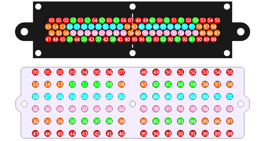
The fiber optic cables on the rear should be placed in a specific way to ensure that everyone has their logics mapped identically. To make this simpler I have built in a 'Testpattern Mode' into the code. On the Rear AVR board, remove the S3 jumper (if it exists) and turn the DELAY trimmer completely counter-clockwise. Restart and you should see a color pattern like this for a few minutes (you may need to reset the AVR board occasionally to get back to this pattern during assembly)...

Now, starting from the center and working outwards, fibers should be routed through the outer bezel and into the inner bezel so the color pattern on the outer bezel ends up looking like this...

The outer-most fibers shown in blue and pink will be the trickiest to position, so take extra care (and time) with those. Again, a small needle-nose pliers or strong tweezers can come in very useful when positioning the fibers.
Note: The numbering below is only for the very first run of boards. Newer versions have slightly different layout.
If after assembly you find that the middle of the RLD is bowed out, don't panic! Loosen the two spacer screws a few turns and the bowing should subside slightly. When mounting the assembly to your logic surrounds the bowing should disappear.
#Assembly (3) Mounting
WARNING! Several builders have encountered problems when mounting the Rear Logic assembly to its surround. While tightening the assembly to the surround the threaded insert has loosened and slipped out; in some cases losing all the precious fiber-optics! Take care when tightening the nuts; turn them slowly and watch the threaded insert at all times. A drop of glue around the insert may help. This problem is more common where the rear bezel has bowed during assembly and does not affect the front assembly.
Hardware Required:
- (14) M3 set screws (16mm long)
- (14) M3 hex nuts and plastic washers
Screw the set screws into the mounting holes of the logic surrounds (4 for each front logic, 6 for the rear logic). Tighten using a 1.5mm hex key. If the set screws appear a little loose in the surround you may want to use a drop of threadlocker fluid.
Place the clear screen over the set screws, then position the logic engine assembly in place. The set screws will go through the outer bezel, leaving enough thread to be secured with the hex nuts. The hex nuts can prove to be very tricky to place and tighten - it may help to find someone with small fingers and bribe them into helping. Another trick is to hook the nut onto the end of your 1.5mm hex key, then place the key onto the set screw; this prevents the nut from falling while you position and tighten it.
#Basic Usage
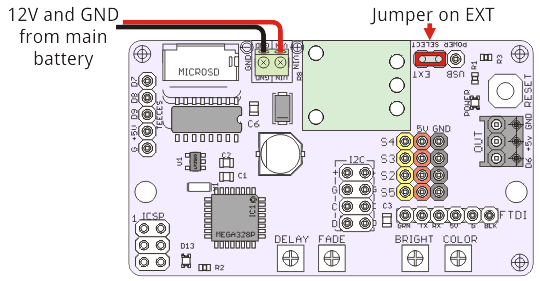
##Powering The AVR board features an efficient regulator module that is capable of supplying plenty of current (up to 2.25A) to the AVR and LED boards. It can take an input voltage between +6V and +17V, so you can safely connect power from a 12V battery.
##Standard Settings
The AVR board can be set to produce standard R2-D2 logic colors and speeds for both the Front (FLD) and Rear (RLD) Logic Displays.
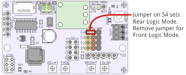
By default the AVR board will output FLD colors (black, blues, whites) & speeds. Placing a jumper/shunt on the S4 pin switches it to RLD mode (slower black, greens, yellows, reds).
##Custom Settings The BRIGHT and COLOR trimpots on the AVR board are used to adjust global brightness and hue values of all LEDs.
Using a small screwdriver to turn the BRIGHT trimpot completely counter-clockwise sets the LEDs to their darkest levels (ie black). Turning the BRIGHT trimpot slowly clockwise will increase brightness until the maximum brightness is achieved. This maximum brightness value is set to 50% of the LED's possible brightness. This limit is in place to keep current consumption and heat generation down, and also to prevent anyone from being blinded (they're insanely bright at 100%!!). A custom settings file on the microSD card can be used to bypass this safety feature and get 100% brightness - this not recommended for long periods of time so do so at your own risk.
Similarly turning the COLOR trimpot completely counter-clockwise sets the color palette to their default hues (FLD will be black/blue/white, RLD will be black/green/yellow/red). Slowly turning the COLOR trimpot clockwise will shift the hues of all colors through the full color spectrum, finally arriving at the same default hues again when turned completely clockwise.
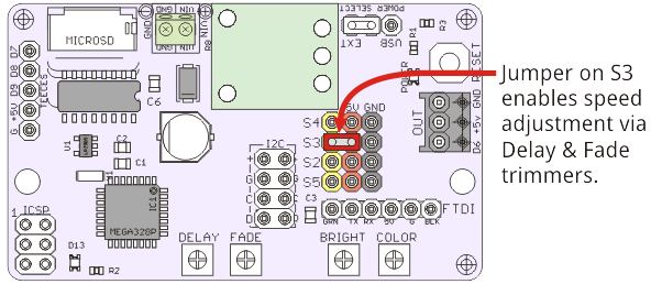
Additionally, if different speeds are desired a jumper can be placed on the S3 pin to enable the DELAY and FADE trimpots. Delay controls how long each key color is paused for. Fade controls how long each "tween" color is paused for - this adjusts how long each key color takes to cross-fade into the next color. When turned completely counter-clockwise the LEDs will behave fastest, turning clockwise slows the LEDs.
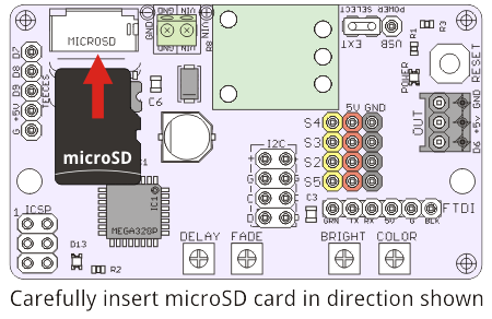
Additional custom settings (such as specific color palettes) may be set by editing the settings.txt file on the microSD card. The microSD card is optional and not needed for basic functionality.
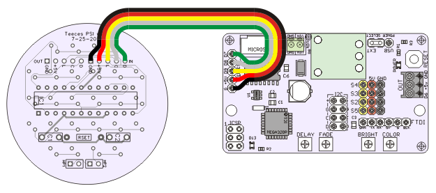
##Connecting a Teeces PSI The AVR board is also programmed to run a Teeces v3.2 PSI if you have one. To get your PSI running, just connect it using a 5-pin jumper cable like this...
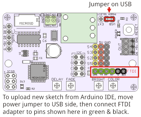
##Updating For basic functionality, the AVR board should never need to be reprogrammed. If, however, a future update should be released or you just like to play with the code, the AVR board can be reprogrammed using the Arduino IDE and an FTDI adapter. In the Arduino IDE software you should select 'Arduino UNO' from the Tools->Board menu.
The basic Arduino sketches are available on the repository here.
#Development Notes This system is basically an Arduino running a bunch of WS2812B LEDs. WS2812B's require only one data wire from a microcontroller to run dozens (maybe hundreds) of the RGB LEDs. We use functions from the [https://code.google.com/p/fastspi FastSPI_LED2 Library] to control all the LEDs, assigning them HSV (Hue Saturation Value) color values and address each LED in the order it is wired.
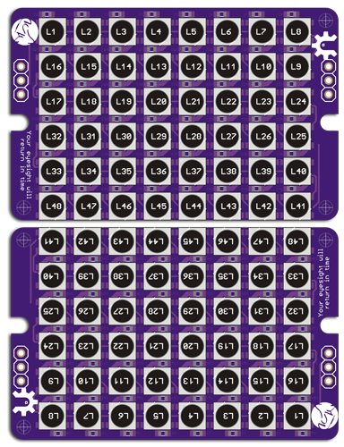
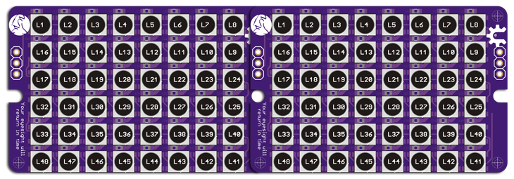
In order to pack all the LEDs to closely on the PCBs, they have been wired in a serpentine configuration. Each LED board has 48 LEDs. For the Front Logic two boards are connected via a 3-pin jumper cable and the top row of LEDs is unused on each logic. For the Rear Logic two boards are soldered together side-by-side and all 96 LEDs are used. These odd configurations are simplified in the software by mapping the physical LED numbers to typical matrix numbering.