Influx and MQTT sensor integration with Atrium
There are many popular sensors for measuring environmental data such as temperature, humidity, air pressure, and electrical air-resistance. Atrium currently supports the DS18B20 (1-wire sensor for temperature measurement), the DHT family of devices, and the Bosch Sensort Tech sensors BMP280, BME280, and BME680 as I2C devices.
The DS18B20 is water-proof, but only provides temperature measurement. The Bosch sensors all provide temperature and air-pressure measurement. In addition, the BME280 and BME680 provide humidity information, and the BME680 furthermore provides electrical air-resistance. The DHT family of sensors should be avoided, as they tend to break easily and are much less precise (personal experience).
So if you want to measure only temperature, you can go with the DS18B20, which has the advantage that you can attach several of those senosrs to a single Atrium device. If you need air-pressure, humidity or electrical air-resistance in addition, then go with one of the Bosch sensors. These sensors, attached as I2C devices, can be configured via one of their pins with 2 different addresses. So it is possible to attach two of these Bosch sensors to an an I2C bus of an Atrium device. Additionally, Atrium can be configured to provide multiple I2C busses.
The following sections will show you how to setup Atrium with several 1-wire devices or a single Bosch sensor and send their measurements to Influx and MQTT.
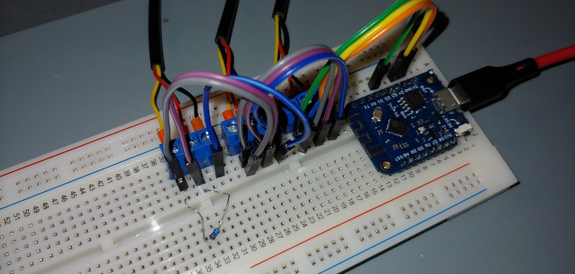
To setup a 1-wire bus with several DS18B20, attach the sensors in parallel, and add a single 5k Ohm resistor between the signal line of the 1-wire bus and its supply. Currently, only active mode is supported. Parasite mode which does not require a dedicated supply may be added later.

The test setup for this demo looks like this: there are 3 DS18B20 attached to a D1 Mini on a breadboard. The signal line is connected to GPIO4 and the 1-wire bus requires a 5k Ohm resistor between 5V and the 1-Wire line.

To configure the hardware execute hwconf set onewire.gpio 4 on the device's serial console and store the config with hwconf write. After that you need to reboot to activate the configuration.

Then you need to scan for the attached 1-wire devices once, unless you
want to manually configure them in the config. For this you can also
enable debugging of the one-wire module using debug -e owb.
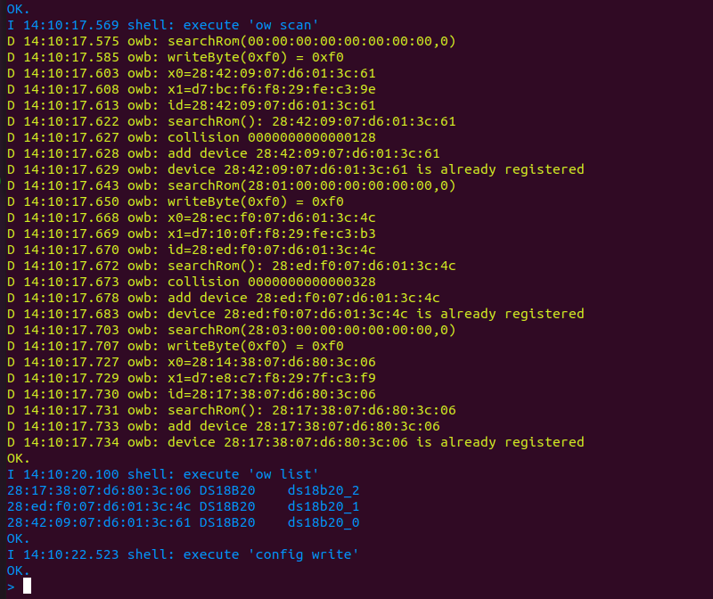
After scanning for the devices, you can find their provided actions in the
list of actions. Just type action -l to see them.

If you want, you can set names for the individual devices. E.g. use
config set owdevices[0].name outside to set the name of the first
1-wire device to "outside". Don't forget to save the configuration with
config write and reboot the device after changing the names.
After reboot we can see in the list of actions that the renamed device now uses its previously set name for its action. For every DS18B20 you will see a "!convert" and a "!read" action.
To read data from your sensors, first trigger the convert action, then
the read action. This wlll update their data in the central sensor data
that can be printed as JSON with the webdata command. See
below:

To publish this data either to an MQTT server or to an Influx database, you need to configure mqtt or influx accordingly. See a sample config procedures below. The warning concerning the unknown action can safely be ignored. MQTT will start anyway when requested, and the warning disappears after writing the configuration and rebooting.
So finally, we need to setup a timer to perform periodic sampling of data and to send it to Influx and MQTT. Do this as shown below:
ow list
timer -c sensortimer 5000 true true
event -a sensortimer`timeout ds18b20_0!sample
event -a sensortimer`timeout ds18b20_1!sample
event -a sensortimer`timeout outside!sample
event -a sensortimer`timeout ds18b20_0!read
event -a sensortimer`timeout ds18b20_1!read
event -a sensortimer`timeout outside!read
event -a sensortimer`timeout influx!rtdata
event -a sensortimer`timeout mqtt!pub_rtdata
This sets up a timer called sensortimer with 5000ms cyclic that gets
automatically started upon boot. You could also tie the starting of the
timer to thie wifistation_upevent, so that sampling only begins when WiFi is up and running. To see the sensor measurement values, typewebdata`.

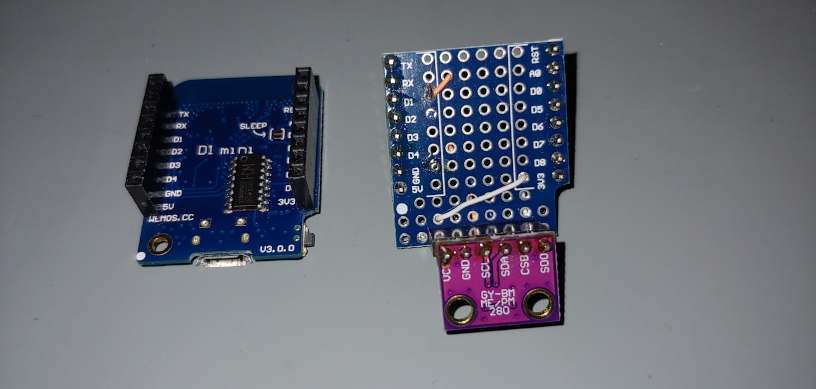
The setup of a BMP280, BME280, or BME680 is quite simple. Just define in
hwconf the I2C interface, and the sensor will be attached during boot.
After that similar actions are available as with the DS18B20 1-wire
sensors. To setup a I2C channel, first add it with hwconf add i2c and
then set its GPIOs with hwconf set i2c[0].sda 4 and hwconf set i2c[0].scl 5. The name of the actions is as the name of the device,
which is the sensor type if there is only one I2C sensor on the bus.
Otherwise, the bus and sensor address will be added to the name to
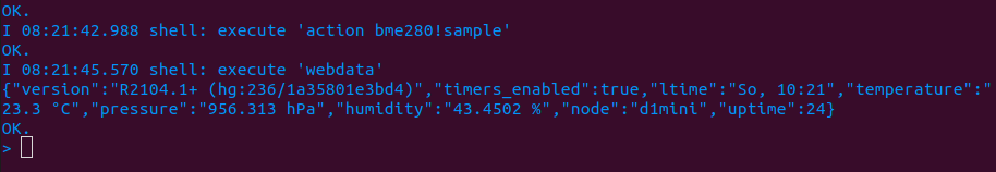
uniquly identify each sensor. Reading the data from a BME sensor just
requires one command. E.g. action bme280!sample. After that all sensor
data are available and will be passed on to MQTT or Influx with the
relevant actions.


Once the data has been sent to your MQTT server or Influx DB, you can use off-the shelve tools to visualize the data. See below the screenshots of smartphone apps for MQTT and Grafana. The MQTT screenshot show the measurement in my home for various rooms and the state of my S20 smart-sockets. The Grafana shot visualizes the time-plot of the sensor data that is recorded be an Influx DB in an raspberry pi.

