Temperature Monitoring
Our heating installation is attached to a district heating system. As the district heating system failed to work in the past a couple of times, I set up an Atrium system and attached 2 DS18B20 sensors to the incoming and outgoing heat pipes, so that I can monitor on Grafana using the Influx DB recording, when a failure started and ended. Additionally, the temperature sensors enable me to do observe the heating performance itself.
The first implementation of that system was based on a Wemos Mini D1 board with some additional hand welded wiring for the 1-wire bus of the DS18B20. Additionally, I had more hand soldered little boards with Wemos D1 Mini and BME280 and SGP30 air sensors distributed in different rooms to record environmental data provided by the sensors (temperature, humidity, and air-pressure, CO2, TVOC).
As it turned out that this is a useful setup, I decided to consolidate the different boards and make a 2-layer PCB for these applications that could also attach an OLED to display directly, what is being measured.

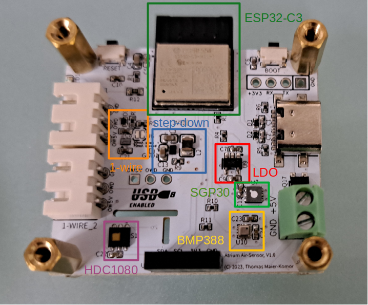
The spec of the new design is as follows:
- SGP30 Sensirion I2C gas sensor for CO2 and TVOC
- HDC1080 Texas Instruments I2C humidity and temperature sensor
- BMP388 Bosch I2C pressure and temperature sensor
- push buttons for reset and display mode switching
- LED for status information
- ESP32-C3 WiFi micro-controller
- TPS62840 Texas Instruments step-down converter
- TPS22946 Texas Instruments current limited high-side to supply power to the 1-wire bus
- TLV70018 Texas Instruments 1.8V LDO for the SGP30
- I2C interface for an OLED SSD1306 display
- AO3401 as an inverse polarity protection for the screw-terminal power
- USB-C connector as alternate power connector and port for debug&development
I would have liked to use the BME288 as I had good experience with it and as it is a combined temperature, humidity, and air-pressure sensor. Unfortunately, it was out of stock at JLCPCB (where I usually order my PCBs), when I designed the PCB. Therefore, I decided to use the TI HDC1080 for humidity measurements. For air-pressure I chose a Bosch BMP388, which unfortunately required a software update, as the register set is different between the BMx2xx and the BMx3xx series. For TVOC and CO2 I stuck with the SGP30, which requires a dedicated LDO as it requires a 1.8V supply

The additional high-side for the 1-wire bus, is just to make sure that a slowly developing short-circuit on the 1-wire bus cannot cause further faults.
The hand welded setup only provided data-recording via Influx and publishing via MQTT. As it is convenient if you can directly read measurements at the device, I also added an interface for a small OLED. Additionally, the boot-mode button can be used to toggle what is displayed on the board, when the firmware is running.

For the main 3.3V supply I use a TPS62840, which is a high-efficient 750mA step-down converter with a tiny DSBGA-6 package. For the 1.8V I use the TLV70018, which is a tiny 200mA LDO that converts the 3.3V from the step-down to 1.8V for the SGP30.
I intended to use one of the temperature sensors (of HDC1080 or BMP388) to measure the air temperature. Texas Instruments includes some advisories for the PCB design and integration of the HDC1080 for that use-case. Their recommendation is to mechanically isolate the sensor on the board with PCB cut-outs from the rest of the system to avoid heat from the micro-controller, LDO or step-down converter to impact temperature measurement. As the overall board is pretty small (43mm x 38mm), I was looking forward to see, how good the mechanical decoupling would be.
In total, there are are 3 temperature sensors on this PCB: HDC1080, BMP388, ESP32-C3. The ESP32 internal one is for measuring the core-temperature, which also gives some insight into how much heat is being spread from the micro-controller. Additionally, it is possible to attach an external DS18B20 to get a comparison value of the air temperature from a sensor that is isolated from any source of heat (micro-controller, LDO, etc.).
So this setup is a good opportunity to compare the values of the different temperature sensors with respect to their location:
- ESP32-C3: on die sensor
- BMP388: close to step-down, LDO, and uC
- HDC1080: decoupled via mechanical cut-outs of the PCB
- DS18B20: off-board sensor completely decoupled from any heat emitting parts
Additionally, I am interested to see how relevant convection for heat dissipation on that low-power board is. The ESP draws about 70mA at 3.3V and the SGP is rated with 48mA at 1.8V dropped down from 3.3V (i.e. about 50mA at 3.3V). Furthermore, the HDC1080 (50uA), the BMP388 (700uA), and the step-down contribute some more heating. But in total this is less than 0.45W.
Doing some measurements, I got following measurement results:
position|OLED|SGP30|core|board|decoupled|external ---|---|---|---|---|---|---|--- flat|attached|on|32.4|27.5|25.0|20.4 vertical|attached|on|29.4|26.9|.24.7|20.4 vertical|attached|off|27.4|22.7|22.8|20.1 flat|none|on|29.3|27.3|24.1|n/a flat|none|off|26.3|21.8|21.4|n/a vertical|none|off|27.3|23.4|23.0|21.7 vertical|none|on|30.3|27.8|24.5|21.5
Some things can be observed here:
- the mechanical isolation helps in reducing the heat introduction from warm components into the sensor, but the board is simply to small to provide adequate isolation to get a real air-temperature reading from an on-board sensor.
- even for this small board, a vertical orientation reduces the core temperature significantly by 2-3 Centigrade.
- The 48mA (spec value) drawn by SGP30 produce in combination with its LDO about 0.16W (the LDO converts the voltage drop from 3.3V to 1.8V into heat) temperature impact on the board resulting in about 3 centigrade higher board temperature.
- For accurate air temperature sensor, an off-board sensor must be used.
As I wanted to have a small main board that equals the size of a 2.4 inch OLED, there is only space for 2 JST-XH connectors for 1-wire sensors. Therefore, I created another daughter board that can be attached below the main board and provides 8 more ports for 1-wire sensors.

Like this I can now measure several heat and return pipes in my heating system and get a more detailed monitoring of it.
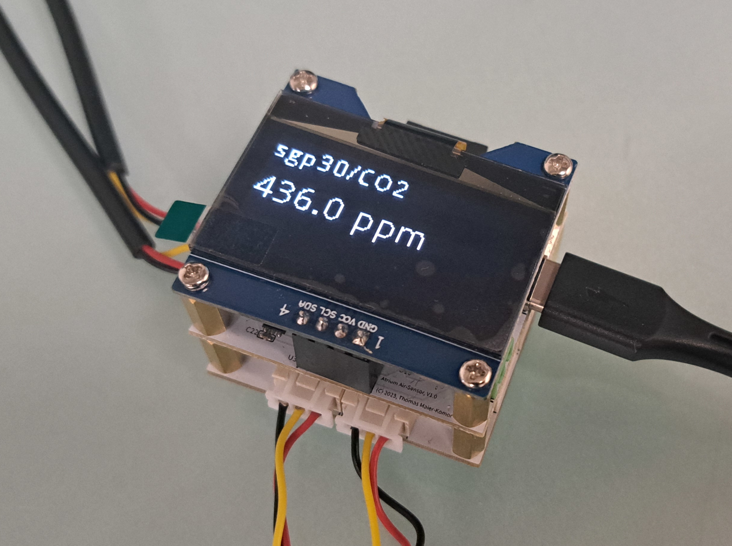
After mounting a fitting OLED and the 1-wire extender, the final stack of PCBs looks likes this:
The hardware configuration is pretty small. All sensors and the OLED are attached via I2C. Only the OLED must be configured explicitly. Additionally, there are GPIOs for 1-wire power, 1-wire over current, and LDO enable. Furthermore the 1-wire bus, the button, and the LED.
Here is the complete hardware config in JSON output format:
{
  "magic":2924801483,
  "gpios":[
      {
        "name":"owoc",
        "gpio":10,
        "config":140
      },
      {
        "name":"en1v8",
        "gpio":8,
        "config":97
      },
      {
        "name":"owen",
        "gpio":1,
        "config":1
      }
  ],
  "button":[
      {
        "name":"button",
        "gpio":9,
        "pull_mode":3
      }
  ],
  "led":[
      {
        "gpio":3,
        "name":"status"
      }
  ],
  "i2c":[
      {
        "sda":5,
        "scl":6,
        "freq":400000,
        "xpullup":true,
        "devices":[
            3840
        ]
      }
  ],
  "onewire":{
    "gpio":0
  },
  "display":{
    "type":"dt_sh1106",
    "options":16,
    "maxx":132,
    "maxy":64
  }
}
In December 2023 I found out that there is a new SGP40 sensor with less than 3mA power consumption that also runs on a 3.3V rail. Additionally, the BME280 is back in stock. So maybe I'll give this board even an update.
Additionally, having a nice little box for that board stack would be nice. So doing a 3D printed case would be appealing. Unfortunately, I am not so much into the mechanics...
For now I am happy with what I have.