RGB Control
The RGB-Control board shown below can drive an RGB-LED-strip and set its color interactively using buttons, a rotary encoder, and a display. The Atrium firmware therefore provides the necessary drivers and infrastructure, which just need to be configured for this specific application. The concept of configurable state-machines, events, and actions makes it possible to setup very flexible applications.
Having a single firmware image configured for a specific application, makes it possible to use roll out firmware updates across multiple embedded hardware and applications without having to rebuild for all different setups. The article below, shows how to configure hardware and software in Atrium. The demonstrated approach is a major advantage of Atrium over Arduino based implementation that require one software for every individual application.
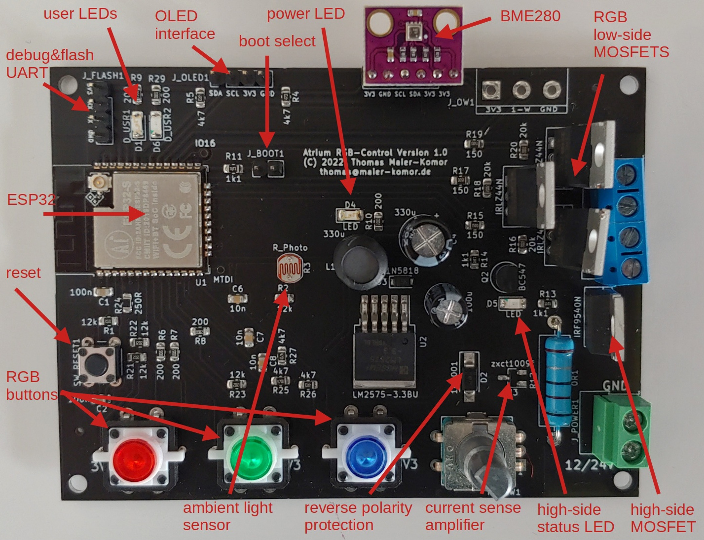
The RGB-Control board provides:
- an ESP32
- 3 low-side MOSFETs
- a high-side MOSFET
- a current sensor
- a light sensor
- a rotary-encoder
- 3 push-buttons with LEDs
- additional status LEDs
- an interface for a BME280 module
- an interface for an OLED display
- a debug and flashing UART interface
Below you can see how to configure the Atrium firmware without writing a single line of code to provide a user-interface for adjusting an RGB strip interactively, using the display, the buttons, and the rotary encoder. This is done by setting up a state-machine that routes events of the rotary encoder and buttons to either of the 3 PWM drivers for the RGB low-side MOSFETs. The adjusted value can be observed on the display in parallel.
- wiring setup for flashing
- flashing the Atrium firmware
- configuring drivers
- runtime setup
- make sure your UART adapter is in 3.3V mode
- connect GND
- connect TX to RX and RX to TX
- supply power either via the 3.3V pin on the UART console header or via the 12V supply screw terminal
To flash the Atrium firmware the ESP32 must be brought into flashing mode. For the RGB-Control board this is done, by shorting the boot jumper and pressing the reset button before every flash command.
Before flashing Atrium the first time, it is advice to perform a full flash erase on the device. Be sure to have a backup of the flash in case you want to restore the original flash after testing Atrium. To erase the flash execute the following command:
esptool erase_flash
You can either perform a full flash of all partitions with one command or flash the individual partitions with separate commands as show below. For a full flash of all partitions execute the follwing command:
esptool write_flash 0x0000 boot-esp32@0x0000.bin 0x8000 ptable-esp32@0x8000.bin 0x100000 atrium.bin
The separate flash commands are as follows:
- setup the partition table (only needed once)
esptool write_flash 0x8000 ptable-esp32@0x8000.bin
- bootloader (only needed if a bootloaded update is required)
esptool write_flash 0x0000 boot-esp32@0x0000.bin
- NVS The NVS partition saves non-volatile-storage across reboots and power cycles. It stores all configuration data. This enables Atrium firmaware updates to be performed independet of the configuration, and therefore keep the configuration persistent and share a single application image with multiple different hardware and software setups.
The partition contents can be created with the atriumcfg tool or just initalized empty, if you want to perform the setup on the target. Below is an example of how to create the NVS partition image.
# set your IDF path - e.g.
$ export IDF_PATH=/work/idf-esp32
# start atriumcfg
$ atriumcfg
# Configure hardware and software in atriumcfg as shown in the next sections.
# Create the partition:
> genpart my-nvs.bin
# exit atriumcfg
> exit

# write nvs partition file to your ESP device
> esptool write_flash 0x9000 my-nvs.bin
- application Write the application image to its location.
esptool write_flash 0x100000 atrium.bin
To configure the hardware you can either use the supplied NVM image, use the hex-dump of the prepared config or follow the manual steps below.
For manual configuration you can either use the config tool atriumcfg,
which means you have to download the config to the target or you can
perform the configuration on the target directly. If you use the config
tool, you can omit the prefixed hwconf on every line, but you have to
switch to the hardware configuration in atriumcfg using the hw
command.
# configure the current measurement ADC
> hwconf add adc.channels
> hwconf set adc.channels[0].name current
> hwconf set adc.channels[0].ch 0
> hwconf set adc.channels[0].unit 1

# configure the ambient light ADC
> hwconf add adc.channels
> hwconf set adc.channels[1].name amblight
> hwconf set adc.channels[1].ch 3
> hwconf set adc.channels[1].unit 1

# configure the rotary encoder
> hwconf add button
> hwconf set button[0].name rotenc
> hwconf set button[0].gpio 13
> hwconf set button[0].dt 14
> hwconf set button[0].clk 27

# configure the color buttons
> hwconf add button
> hwconf set button[1].name btnr
> hwconf set button[1].gpio 34
> hwconf add button
> hwconf set button[2].name btng
> hwconf set button[2].gpio 35
> hwconf add button
> hwconf set button[3].name btnb
> hwconf set button[3].gpio 26

# configure the LEDs on the buttons
> hwconf add led
> hwconf set led[0].name swledr
> hwconf set led[0].gpio 32
> hwconf add led
> hwconf set led[1].name swledg
> hwconf set led[1].gpio 33
> hwconf add led
> hwconf set led[2].name swledb
> hwconf set led[2].gpio 25

# configure the status LED
> hwconf add led
> hwconf set led[3].name status
> hwconf set led[3].gpio 23

# configure the application LED
> hwconf add led
> hwconf set led[4].name appled
> hwconf set led[4].gpio 23

# configure the PWM channels
> hwconf add led
> hwconf set led[5].name red
> hwconf set led[5].gpio 4
> hwconf set led[5].pwm_ch 0
> hwconf add led
> hwconf set led[6].name green
> hwconf set led[6].gpio 15
> hwconf set led[6].pwm_ch 1
> hwconf add led
> hwconf set led[7].name blue
> hwconf set led[7].gpio 17
> hwconf set led[7].pwm_ch 2

# configure the high-side MOSFET, which is shared across all LEDs
> hwconf add led
> hwconf set led[8].name hss
> hwconf set led[8].gpio 2
> hwconf set led[8].config.active_high 1

# configure the I2C bus
> hwconf set i2c.sda 19
> hwconf set i2c.scl 18

# configure the display
> hwconf set display.type dt_ssd1306
> hwconf set display.maxx 128
> hwconf set display.maxy 64
# set display option alternating rows (see ssd1306.h)
> hwconf set display.options 0x10

# finally make the config persistent
> hwconf write

# and reboot to activate the configuration
> reboot
Once the hardware configuration has been performed and activated (via
rebooting), all drivers should provide their necessary events and
actions that are needed for the run-time configuration. You can use
event -l and action -l to list available actions and events
accoringly.
Below follows an example how the configured drivers can be setup with a state machine to allow easy user interaction for setting the RGB values on the LED strip and storing and restoring the related PWM values.
# add state machine
> sm add ui

# add states of state machine
> sm add ui main
> sm add ui red
> sm add ui green
> sm add ui blue

# turn on/off associated led on button on state enter/exit
> event -a ui:red`enter swledr!on
> event -a ui:red`exit swledr!off
> event -a ui:green`enter swledg!on
> event -a ui:green`exit swledg!off
> event -a ui:blue`enter swledb!on
> event -a ui:blue`exit swledb!off

# set pwm value of relevant channel when turning rotary encoder
> sm on ui:red rotenc`left red!dec
> sm on ui:red rotenc`right red!inc
> sm on ui:green rotenc`left green!dec
> sm on ui:green rotenc`right green!inc
> sm on ui:blue rotenc`left blue!dec
> sm on ui:blue rotenc`right blue!inc

# buttons in main
> sm on ui:main btnr`short sm!set ui:red
> sm on ui:main btng`short sm!set ui:green
> sm on ui:main btnb`short sm!set ui:blue

# buttons in red
> sm on ui:red btnr`short sm!set ui:main
> sm on ui:red btng`short sm!set ui:green
> sm on ui:red btnb`short sm!set ui:blue

# buttons in green
> sm on ui:green btnr`short sm!set ui:red
> sm on ui:green btng`short sm!set ui:main
> sm on ui:green btnb`short sm!set ui:blue

# buttons in blue
> sm on ui:blue btnr`short sm!set ui:red
> sm on ui:blue btng`short sm!set ui:green
> sm on ui:blue btnb`short sm!set ui:main

# backup pwm states on exit
> event -a ui:red`exit red!backup
> event -a ui:green`exit green!backup
> event -a ui:blue`exit blue!backup

# set the rotary left event to turn off all channels in default mode
> sm on ui:main rotenc`left red!off
> sm on ui:main rotenc`left green!off
> sm on ui:main rotenc`left blue!off

# set the rotary right event ot restore the saved PWM state on all channels
> sm on ui:main rotenc`right red!restore
> sm on ui:main rotenc`right green!restore
> sm on ui:main rotenc`right blue!restore

# set the dimmer step interval to 20ms
> config set dim_step 20

# a short click on the rotary encoder should toggle the display mode
> event -a rotenc`short display!set_mode

# a medium click on the rotary encoder should display the time
> event -a rotenc`med display!set_mode time

# medium pressing a color button should backup the current PWM value
> event -a btnr`med red!backup
> event -a btng`med green!backup
> event -a btnb`med blue!backup

# medium pressing a color button should also blink the appled twice
# so that the user gets a feedback that the value was stored to NVM
> event -a btnr`med led!set appled:twice
> event -a btng`med led!set appled:twice
> event -a btnb`med led!set appled:twice

# store the configuration
> config write

# and reboot to activate the config
> reboot