8x8 pixel matrix display
The upper board of NIBO Burger is equipped with a slot for ARDUINO shields and nicai-systems provides an 8x8 pixel LED matrix display for that slot. This page describes how the display works and how it can be accessed.
 Image source
Arduino shields are boards that can be plugged on top of the Arduino PCB or in our case on the upper board of NIBO Burger for extending its capabilities. Every Arduino shield must have the same form-factor as the standard Arduino. NIBO Burger provides following signals:
The following picture represents on the left side an electrical schematic extract of NIBO Burger and on the right side the same interface from the 8x8 pixel matrix display. One can see the pins of the burger and the display fit together. Although the burger has more pins assigned, the common pins match each other.
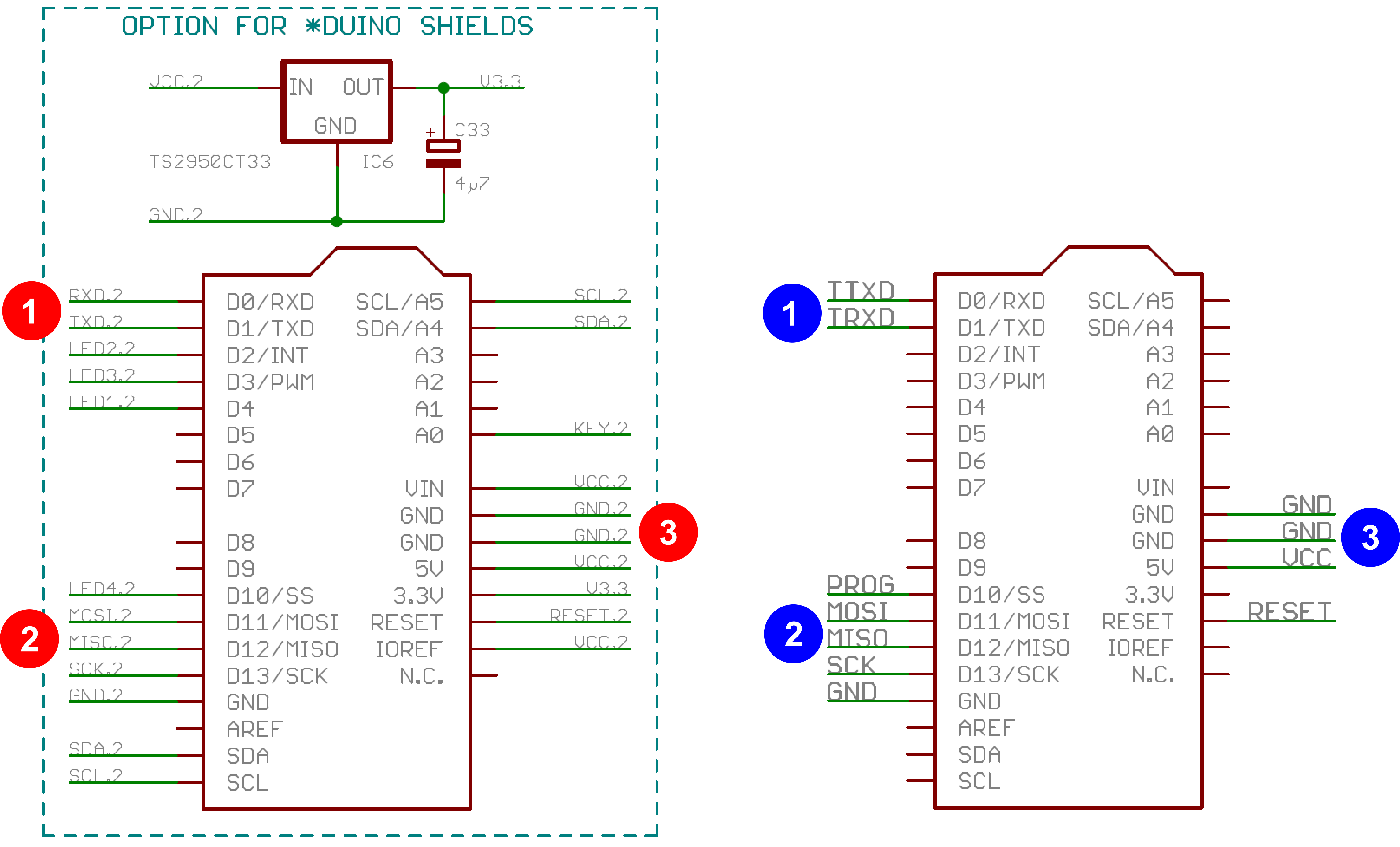
The following table shows the pins of the NIBO Burger and the matrix display in detail with a short description.
| PIN | Burger | Display | Description |
|---|---|---|---|
| 1 | red | blue | |
| D0/RXD | RXD.2 | TTXD | UART communication RX on Burger is TX on display |
| D1/TXD | TXD.2 | TRXD | UART communication TX on Burger is RX on display |
| D2/INT | LED2.2 | - | |
| D3/PWM | LED3.2 | - | |
| D4 | LED1.2 | - | |
| 2 | red | blue | |
| D10/SS | LED4.2 | PROG | SPI communication SS: Slave Select (often active low, output from master) |
| D11/MOSI | MOSI.2 | MOSI | SPI communication MOSI: Master Output Slave Input, or Master Out Slave In (data output from master) |
| D12/MISO | MISO.2 | MISO | SPI communication MISO: Master Input Slave Output, or Master In Slave Out (data output from slave) |
| D13/SCK | SCK.2 | SCK | SPI communication SCLK: Serial Clock (output from master) |
| GND | GND.2 | GND | Ground connection |
| SDA | SDA | - | I²C bus serial data Not populated on display (only Burger is I²C bus capable) |
| SCL | SCL | - | I²C bus serial clock Not populated on display (only Burger is I²C bus capable) |
| 3 | red | blue | |
| SCL/A5 | SCL.2 | - | |
| SCL/A4 | SDA.2 | - | |
| A0 | KEY.2 | - | |
| VIN | VCC2 | - | |
| GND | GND.2 | GND | Ground connection |
| GND | GND.2 | GND | Ground connection |
| 5V | VCC2 | VCC | 5VDC source |
| 3.3V | V3.3 | - | 3.3VDC source |
| RESET | RESET.2 | RESET | Reset connection that does a soft reset on the shield. |
| IOREF | VCC.2 | - | This pin provides the voltage reference with which the microcontroller operates. A properly configured shield can read the IOREF pin voltage and select the appropriate power source or enable voltage translators on the outputs for working with the 5V or 3.3V. |
Today a printer is connected to a PC mostly via USB cable, but can you remember when thick cables with clunky connectors were used? Those printers probably were using UART to communicate with the PC.
UART stands for Universal Asynchronous Receiver/Transmitter. It’s not a communication protocol like SPI and I2C, but a physical circuit in a microcontroller, or a stand-alone IC. A UART’s main purpose is to transmit (TX) and receive (RX) serial data.
One of the best things about UART is that it only uses two wires to transmit data between devices.
UARTs transmit data asynchronously, which means there is no clock signal between the two devices that communicate. Therefore, both devices must work with the same Baud rate (frequency) and data package size.
Each packet contains 1 start bit, 5 to 9 data bits (depending on the UART), an optional parity bit, and 1 or 2 stop bits. The following example shows a data word with 7 data bits:

Image source
A German video, which is helpful regarding the following content, can be found here.
Start bit
The UART data transmission line is normally held at a high voltage level when it’s not transmitting data. To start the transfer of data, the transmitting UART pulls the transmission line from high to low for one clock cycle. When the receiving UART detects the high to low voltage transition, it begins reading the bits in the data frame at the frequency of the baud rate.
Data frame (bits 0 up to 7)
The data frame contains the actual data being transferred. It can be 5 bits up to 8 bits long if a parity bit is used. If no parity bit is used, the data frame can be 9 bits long. In most cases, the data is sent with the least significant bit first.
Parity
Parity describes the evenness or oddness of a number. The parity bit is a way for the receiving UART to tell if any data has changed during transmission. Bits can be changed by electromagnetic radiation, mismatched baud rates, or long-distance data transfers. After the receiving UART reads the data frame, it counts the number of bits with a value of 1 and checks if the total is an even or odd number. If the parity bit is a 0 (even parity), the 1 bits in the data frame should total to an even number. If the parity bit is a 1 (odd parity), the 1 bits in the data frame should total to an odd number. When the parity bit matches the data, the UART knows that the transmission was free of errors. But if the parity bit is a 0, and the total is odd; or the parity bit is a 1, and the total is even, the UART knows that bits in the data frame have changed.
Stop bits
To signal the end of the data packet, the sending UART drives the data transmission line from a low voltage to a high voltage for at least two bit durations.
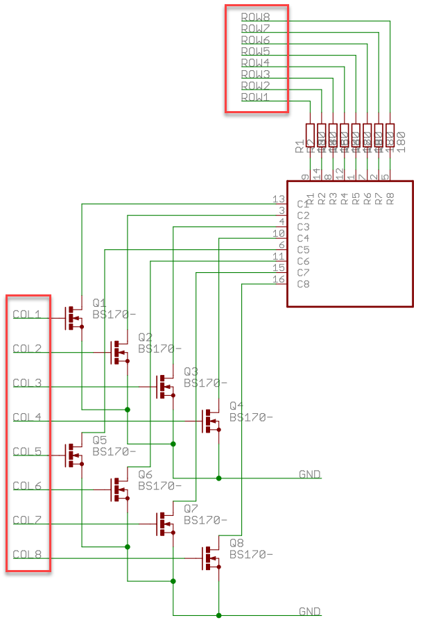
NIBO Burger LED Matrix comes with 8 x 8 LEDs. If one wants to control each LED individually, 8 x 8 = 64 outputs on the controller are needed. However, in the current case only 2 x 8 = 16 outputs are used for controlling 64 LEDs as the schematic below proves. This approach is called matrix multiplexing.
For simplicity purpose we will take a 4 x 4 LED matrix for explaining matrix multiplexing. Please see image below. Rows are marked from A to D, columns are from 1 to 4. Now we can address each LED by row and column. Top left led would be (A,1). Bottom down led would be (D,4).
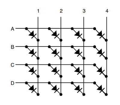
Image source
By multiplexing, only one row of the LED matrix is activated at any one time. During the period in which a given row is energized, the desired LEDs are lit by energizing the appropriate columns. Sometimes this process is known as scanning.
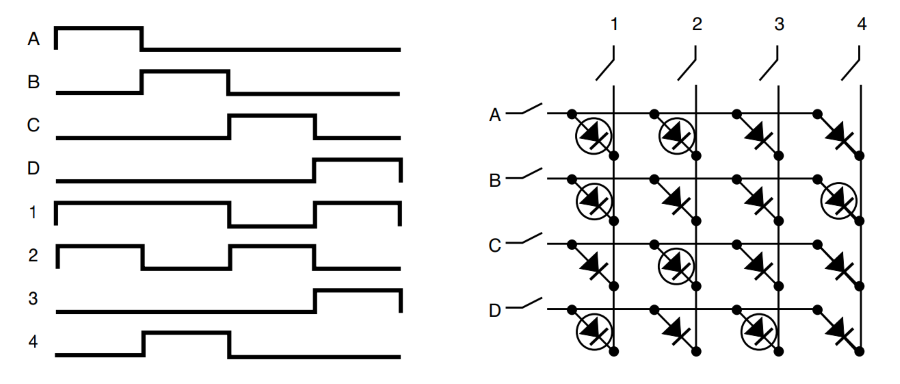
When switching from row to row fast (for example 60 Hz or more) the human eye cannot register the row change. For the observer it looks as if the desired LEDs are permanently on.