E) Rabbit warren thoughts
Line detecting and motor controlling can be realized in a variety of ways. The first thought of most people probably is, using the 3 surface sensors red (right), green (center) and blue (left). When green sensor is on the line, run both motors with same speed. When red (right) sensor is on the line, turn left motor faster and vice versa. One would have 3 states (right, center, left) for controlling the motors.
This could work, but the suggestion of NICAI Systems (manufacturer of NIBO Burger) is different. It works with the green LED only, but with all 3 phototransistors.
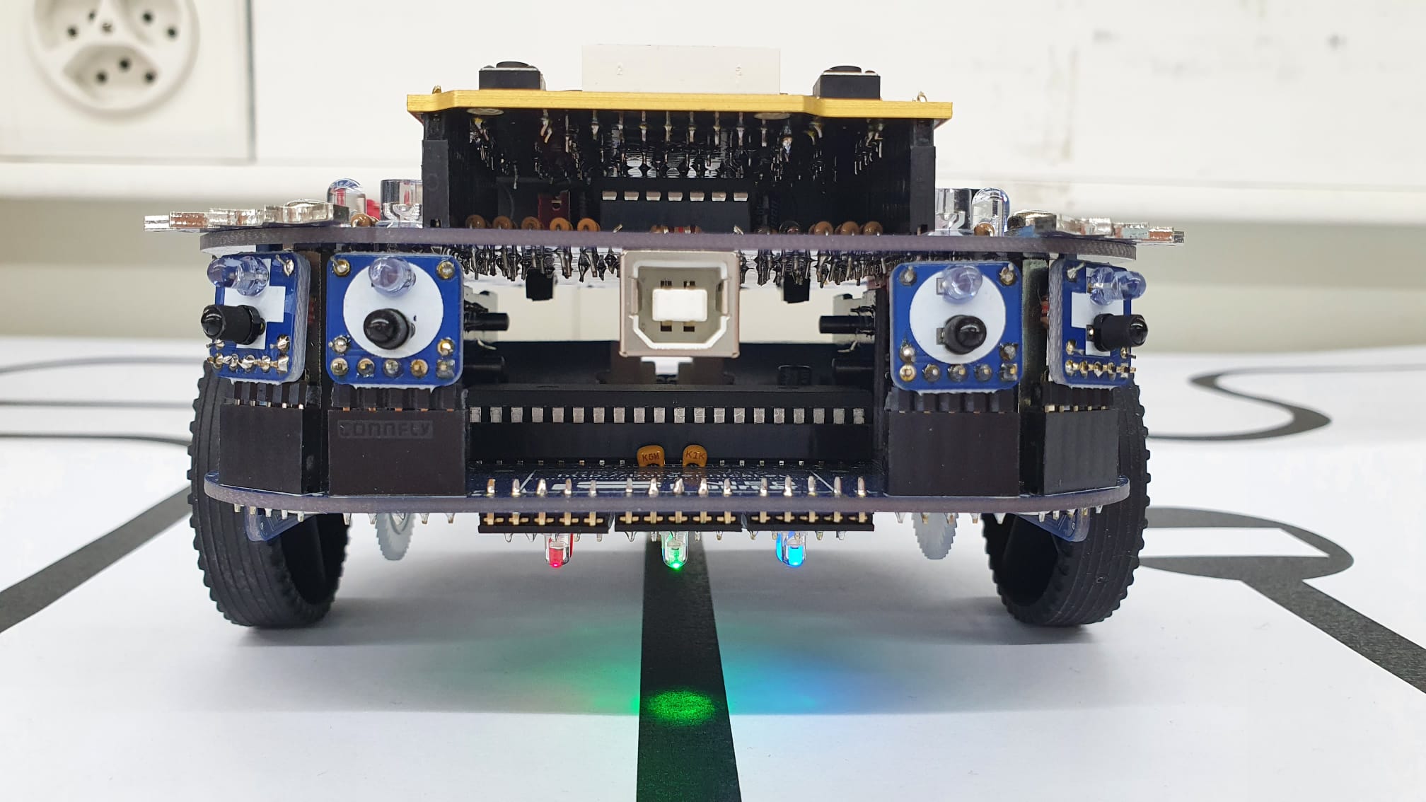 The picture shows the NIBO Burger front with three surface sensors. In running direction, red is on the right and blue is on the left. Green is centered.
The phototransistors on the left and right need to be configured as follows, if they should detect light of the green LED as well.
void setup() {

    // other code here

    surface_init();
    analog_setExtToggleMode(ANALOG_BCL, 1);
    analog_setExtToggleMode(ANALOG_BCR, 1);

    // other code here
}
The values from 0 up to 1023 can be read as follows. Attention, values are clipped off at 127 max.
uint8_t bcl = min(127, surface_get(SURFACE_CL)/8); // Green light on left transistor
uint8_t bl  = min(127, surface_get(SURFACE_L) /8);
uint8_t bc  = min(127, surface_get(SURFACE_C) /8);
uint8_t br  = min(127, surface_get(SURFACE_R) /8);
uint8_t bcr = min(127, surface_get(SURFACE_CR)/8); // Green light on right transistor
Now working with just bcl, bc and bcr is possible to track the line, without using bl and br.
The following picture shows a possible sensor behavior when the line is in centered. Part of the green light is also thrown onto the blue and red phototransistors.
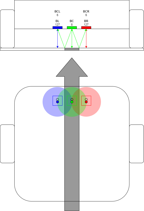
When the line is on the left, BCL value is much lower than the BCR value. Black background is less reflective.

If the line is above the red sensor, it's the other way around.
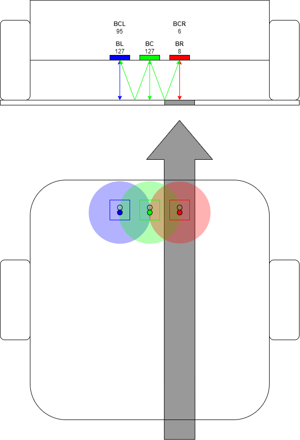
With help of the green light on the red and blue phototransistor a deviation from the ideal line can be recognized early. Furthermore 5 states could be created (not just 3) as follows:
#define FLOOR_VALUE 40                          // Light-gray floor: 40, Medium-gray floor: 30
volatile int8_t state;                          // Value between -2 and +2

// Weak-linking function
void analog_irq_hook() {
    uint8_t bcl = min(127, surface_get(SURFACE_CL)/8);
    uint8_t bl  = min(127, surface_get(SURFACE_L) /8);
    uint8_t bc  = min(127, surface_get(SURFACE_C) /8);
    uint8_t br  = min(127, surface_get(SURFACE_R) /8);
    uint8_t bcr = min(127, surface_get(SURFACE_CR)/8);

    if (bc < FLOOR_VALUE/4) {
        state = 0;                              // Line is in the center
    } else if (bc < FLOOR_VALUE) {
        // Line detected with center sensor
        if (bcl<bcr)  state = -1;               // Line slightly left
        if (bcl>bcr)  state = +1;               // Line slightly right
        if (bcl==bcr) state =  0;               // Line is in the center
    } else {
        // Line lost with center sensor
        if (state==-1) state = -2;              // Line was previously on the left
        if (state==0) state = +2;               // Line was previously in the center (guessing)
        if (state==+1) state = +2;              // Line was previously on the right
    }
}