DIP40 PCB for TT07: what about a breakout like this? #2
Comments
|
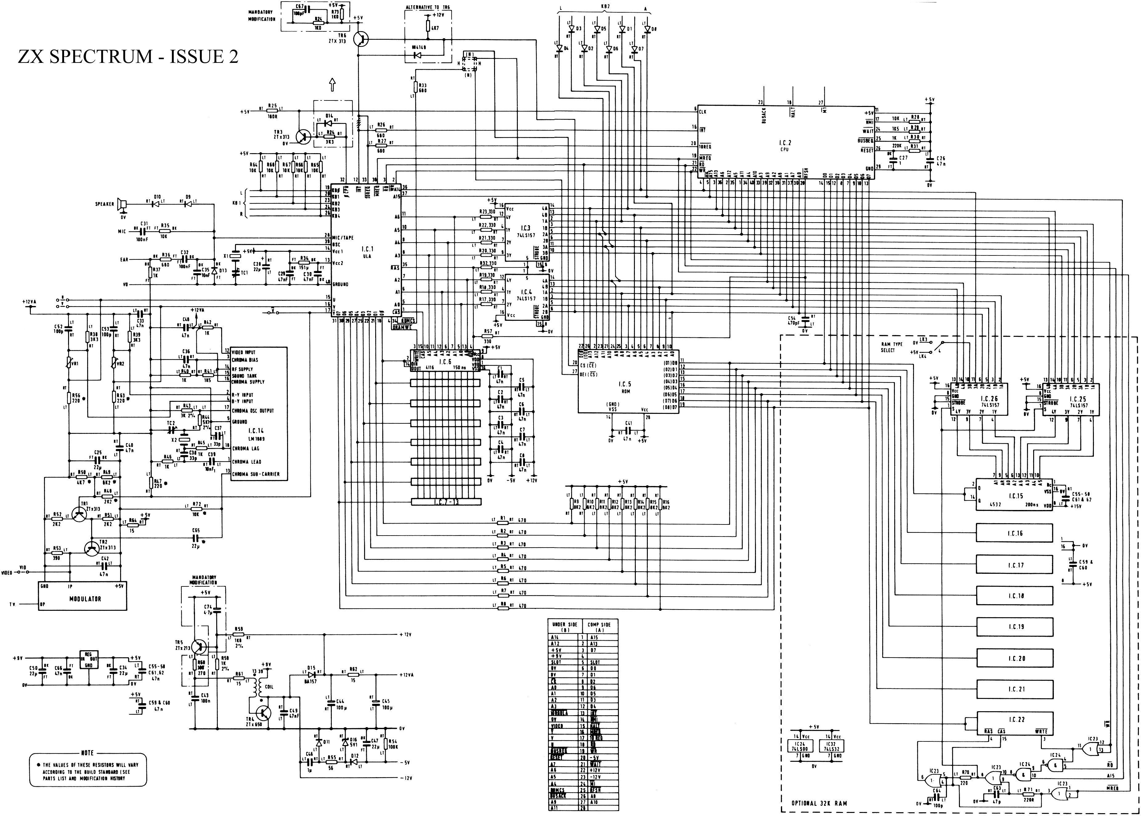
This looks great! Thank you and fingers crossed it fits in DIP40 sized PCB! NOTE, I just realised one issue with my MUX approach combined with ZX Spectrum and frequency multiplier. The clock that is passed to Z80 on ZX Spectrum can be abruptly varying! For example see: See pin 32 from ULA (IC1) feeding into pin 6 of Z80 (IC2). So, I am thinking, maybe it is better to have 2 clock inputs in TT design - one clock to drive internal Z80 core and another (higher) to drive internal multiplexor? In case of ZX Spectrum higher clock could come directly from 14 MHz crystal oscillator instead of multiplier. |
|
For project selection, you may want to go with something like the PY32F002A instead of the ATtiny? Cheaper and the footprint is also smaller (QFN-16), if I'm not mistaken |
|
Hm, I'm not actually seeing where the 3.5MHz clock actually comes from, but the interrupted clock--with no extra signaling just an abrupt hold--does look problematic... Will try and ponder. |
I added some annotation, ZX Spectrum's ULA creates an interrupted 3.5MHz signal to drive Z80 based on 14MHz crystal:
|

ULA creates Z80 clock by dividing its master 14MHz oscillator. But it holds Z80s clock high (measured at Z80 pin) during the video memory contention. https://www.tomas-franke.cz/public/The-ZX-Spectrum-ULA.pdf By the way, I wrote ULA core in Verilog, that is compliant with the book. We can put it on Tiny Tapeout one day. |
Hi,
Playing around with this a bit, am thinking of doing something like this:
The idea is to be as transparent and true as possible, so I'm taking the input clock and multiplying it by 4 to do the multiplexing.
Initial floorplanning says I might, just might, be able to fit this on a 40 pin DIP that would slot right into place (assuming I get to populate the ASIC top side and the rest underneath).
The MCU is there to setup the project through the TT MUX, and manage timing/latches and such, but would not interfere with anything.
It's still prelim and messy but this look like it would make sense to you?
The text was updated successfully, but these errors were encountered: