SP1: very attractive universal multi-company smart plug with energy monitor! #737
Comments
|
that is definitely HLW8012 CURRENT_RESISTOR and VOLTAGE_RESISTOR_DOWNSTREAM values already matches with espurna's default. you should follow the VOLTAGE_RESISTOR_UPSTREAM resistors. |
|
Nice that you confirm that. I have build and uploaded a new firmware called SP1. No I have the problem, that the WiFi works, but no relay, LED and energy monitor because I don't know at all which pins are used at the ESP8266EX. There is not descripting on the board (beside 3.3V, GND, RX, TX and IO0). SO I would need endless build attempts. It would be great if the pins could be soft configured via EEPROM. I have created a new issue for that. Do you think that can work or do you have any othe hint which helps to speed up or is effective? |
|
@knopserl : (for your pins image) |
|
@gn0st1c : you are incrediable and saved me a lot of time! My idea whould have been to write a sketch to set/read all the ports and and measure the signal at the PCB pinout using the serial line for manual interaction. How do you know that pinout? Do you know the PCB or do you have an SP1 or what magic have you applied?
|

|
@knopserl : i'm sure you already know these but;
|
|
@gn0st1c : You're totaly right with your hints. I'm a big step further, but still need some more help, so please be a bit more patient with me :-) I think I have found out the pins and their functions. Here are the setting in hardware.h I'm using: and here the updated pin picture thanks a lot in advance |

|
it seems only setting BUTTON1_RELAY to 1 should fix your problems. (you have 1 button and 1 relay) |
|
@gn0st1c you are just fantastic! The button on/off works now and I did an OTA updload/upgrade.
|

|
accidently closed the issue, sorry |
|
@knopserl : also here is the data sheet for your ESP8266 (S3) |
|
@gn0st1c : here is the screenshot of the web interface, it shows some values but they are nonsens. I have connected a LED lamp with 0,1A and voltage is 230V.
|

|
can you zip and attach your original firmware.bin ? |
|
you can also order one device and I will pay for it (via paypal or whatever you prefer) |
|
well, this was a very interesting decompiling session :) the chip is BL0937. it's pin compatible with HLW8012. you learn something everyday. and here is the datasheet; |
|
you impress me more and more! |
|
@knopserl : i'm in Turkey. |
|
good luck for tomorrow and and greetings from Austria to Turkey, it's an honor to work together with you |
|
Coding seems to be the same, but the calculation, or more precisely, reference values seem to be different (HLW8012 reference voltage is 2.43V while that of BL0937 is 1.218V, as example) Maybe there's a way to use original HLW8012 library and just change reference values? @gn0st1c - all kudos for decompiling/rev engineering. 🥇 |
|
what concerns me a bit is, that the resulted values using the HLW8012 code are completly nonsens or look like it does not work at all (see the Web page screen shot above) Yes kudos goes to @gn0st1c he is doing a great reverse engineering job and gave me the essential hints. I think it's really worth to get this device hacked/supported as it is very well rated/advertised/ranked in many articels and sold under many different brands. I have so far not found anything I like more. |
|
i've "blindly" coded a driver but it needs testing :) |
|
of course, I'm the tester, so how do I get it and how to I include it in my project (I use visual studio code)? |
|
to use it in espurna, you have to add a handler as well. i'll do that later. so just for testing purposes, you can just rename files & variables of the attached files and overwrite your current HLW lib folder. (find replace BL0937 to HLW8012) please note that, i just wrote the code last night and never did a second control pass. it may not work. |
|
I have copied the files to the folder: |
|
try this. if this doesn't work, too you'll have to wait for tonight when i have the time. |
|
this is the result of the latest build
|

|
I have now used another SP1 with the Smartlife App (China cloud) and it shows: 230.8V, 46mA, 6.2W |
|
no worries, we'll make it work. but later tonight. :) |
|
HI As @lobradov pointed out, the HJL01/BL0937 has different configuration parameters but I also found out the SEL pin is inverted (compared to the HLW8012 boards I have checked so far) and the interrupt won't work unless it monitors FALLING edges. Fortunately, all these changes can be configured from ESPurna without the need to changed the library. I have committed my changes to the sensor branch, will join them to dev (and master) as soon as I have some feedback from you. Of course, once @gn0st1c pushes his PR that would be the preferred way to implement it. |
|
Well would you look at that
This is a 75 watt light bulb BTW, my plugs have the following pin config: |

|
@doodah33 What device is yours? A Vanzavanzu (https://www.amazon.com/Smart-Plug-Wifi-Mini-VANZAVANZU/dp/B078PHD6S5)? |
|
xoseperez eres un crack, el puto amo jajaja Anxious I am waiting for the bin |
|
@xoseperez that is exactly it. There are a ton that look like that one, but I couldn't vouch that they have the same components inside. |
|
Pido perdon por mi ingles I apologize for my English |
|
Released with 1.13.0. Closing. |
|
a great and successfull thread! |
|
Y cual es el BIN? And what is the BIN? |
|
You have to use the blitzwolf.bin regards from Austria ;-) |
|
Oohhh gracias, y no lo vi, buscaba algo mas comun como SP1 Oohhh thanks, and I did not see it, I was looking for something more common like SP1 |
|
Hi guys, do anyone know what is the power supply ic used on these smartplugs???? |
|
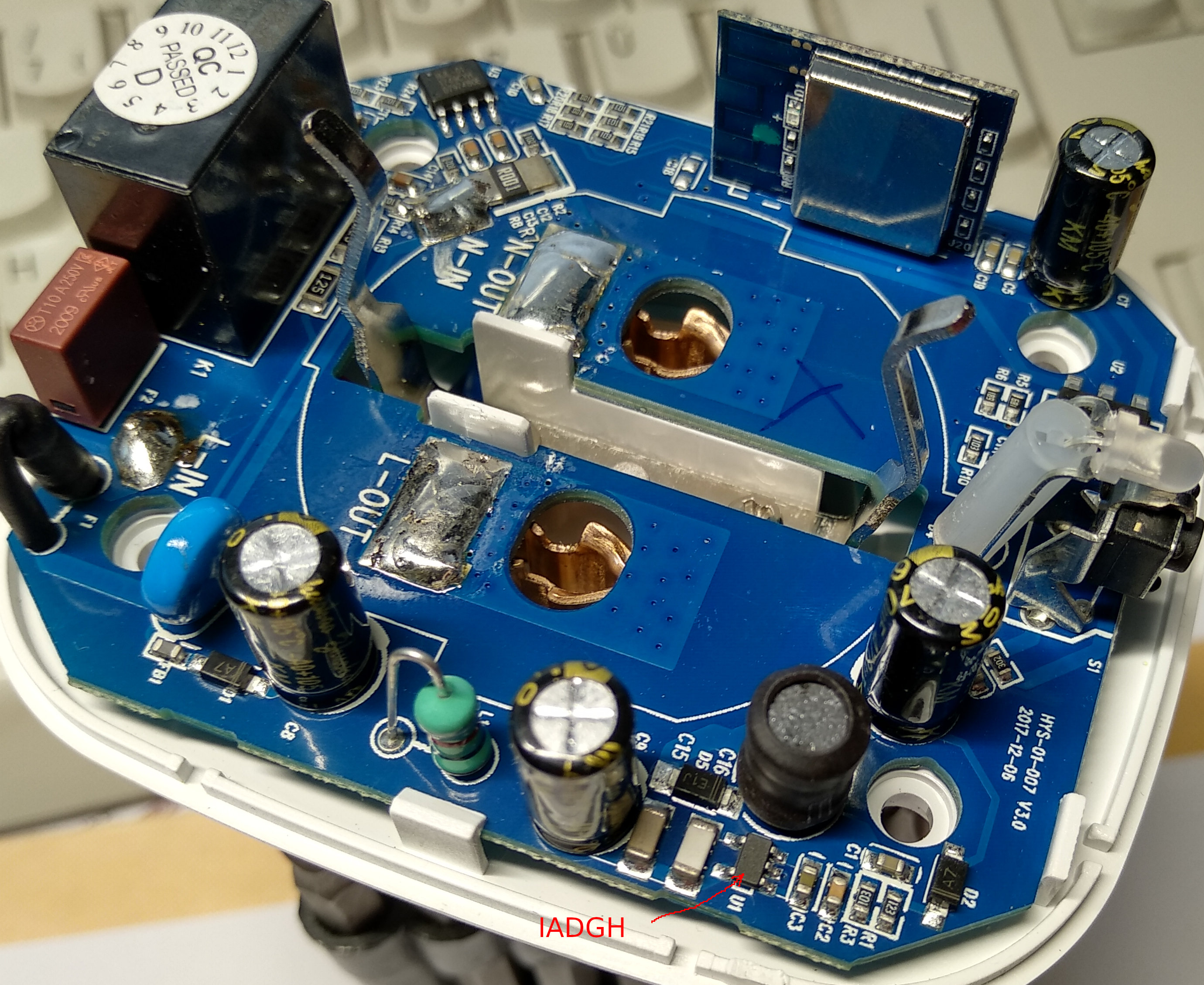

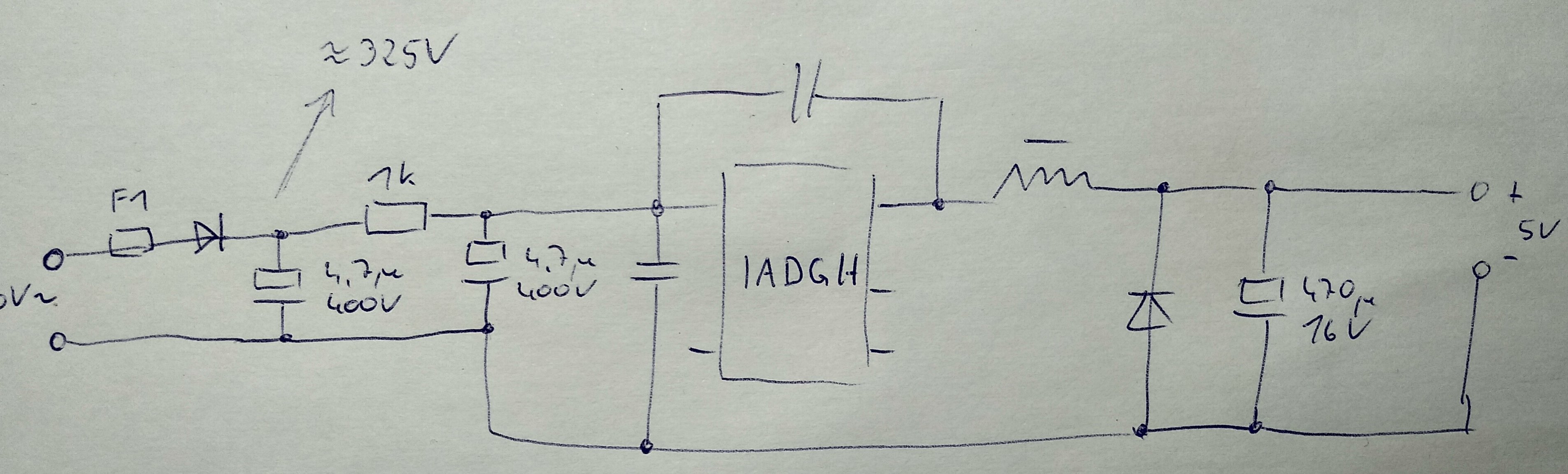
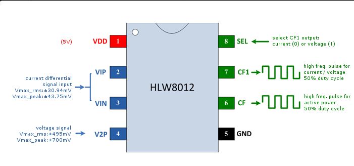
Hello,
there is an ic in SOT-23(5) package. He is named "IADGH". But I don´t
find a datasheet.
I made 2 pictures and a (very) simple schematic. You found them at the
attachment.
Greeting.
Am 12.09.19 um 22:32 schrieb filzek:
… Hi guys, do anyone know what is the power supply ic used on these
smartplugs????
—
You are receiving this because you commented.
Reply to this email directly, view it on GitHub
<#737?email_source=notifications&email_token=AISEBLNSXLQX5IKQKQUOW43QJKRNRA5CNFSM4EX5HRQ2YY3PNVWWK3TUL52HS4DFVREXG43VMVBW63LNMVXHJKTDN5WW2ZLOORPWSZGOD6TFJNY#issuecomment-530994359>,
or mute the thread
<https://github.com/notifications/unsubscribe-auth/AISEBLNISEVJGZRLEIDTIGTQJKRNRANCNFSM4EX5HRQQ>.
|
|
Some folk mentioned they had difficulty finding the manufacturer and data sheet for the BL0937. The manufacturer is Shanghai Belling Co, Ltd. and the data sheet is available on thejir web site here: http://www.belling.com.cn/en/product_info.html?id=138 |
|
@cjheath : also, #737 (comment) |
|
@gn0st1c yes of course thanks, but some folk like to find the manufacturer too. This chip is unusually difficult to find. |
For future reference, here the english datasheet of the BL0937 can be found |
|
Thank you guys for getting the BL0937 to work. I am currently trying to do the same for esphome, and I get the correct results. So @xoseperez approach is to use the untouched HLW8012 library (which uses the HLW8012 formulas to calculate the values) and then apply these ratios on top of it, correct? I would just like to understand and then document, why the factor for calculating pulse width (in microseconds) into power is 1707145 (3414290 / pulse_width_in_us / 2). |
|
@hanzoh have you ever published the results for esphome? |
|
No, I gave up as the results were unsatisfying. The original Gosund firmware gave much better values than any custom Firmware. I don’t know if they use something other than the Interrupt approach. |
|
Hi, @xoseperez @gn0st1c , wonder full thread. Really learned a lot from this. I'm making my own custom board using BL0937 with esp32. The problem I'm facing is this that I'm unable to get any pulse from IC both load connect or disconnected. |
Hi, I have found a very interesting universal smart power plug called SP1. This hase a very good rating and is available from many companies based on a base product SP1. You can find it easily in the web or on Amzon and it's offered from many companies like: Gosund, Homeplug, Coosa etc. It's always the same product and same PCB, I have opened it and soldered power and RX/TX and read the chip id: It's a ESP8266EX with 1M flash and it uses the Smart Life app and a Chinese cloud.
It offers switch and power meter. Unfortunatly it has an energy meter chip labeled (3 lines) which you don't find in the web: HJL-01, J1749CYH, D797480E. Based on the parts around and wiring, I guess its a HLW8012.
It would be extremly attractive to get that working with espurna (might require some reverse engineering) but I'll try it but would be nice if I could get some help to get faster to a result.
Here some links and pictures from inside the plug:
http://www.gosund.com/index.php?m=content&c=index&a=show&catid=6&id=5
https://www.amazon.de/Steckdose-Homecube-intelligente-Verbrauchsanzeige-funktioniert/dp/B076Q2LKHG
https://www.amazon.de/intelligente-COOSA-Stromverbrauch-funktioniert-Fernsteurung/dp/B077RTJJH1/ref=sr_1_1?s=diy&ie=UTF8&qid=1522268132&sr=1-1&keywords=coosa
US version is SP2 (I guess same electronics PCB)
https://www.amazon.com/COOSA-Monitoring-Function-Campatible-Assiatant/dp/B0788W9TDR/ref=sr_1_fkmr0_3?s=hi&ie=UTF8&qid=1522267864&sr=1-3-fkmr0&keywords=coosa+SP1
The text was updated successfully, but these errors were encountered: