GraphStructure
Street and transport networks are represented in OTP using directed graphs. The purpose of this page is to explain how vertices (aka nodes) and edges are arranged to allow finding optimal paths through a complex transportation system.
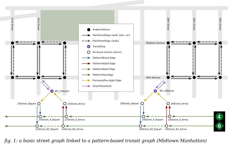
Figure 1 shows a small part of an OTP graph for New York, containing both street and public transit information. In the representation of the street network (derived from OSM data), nodes represent intersections and edges represent road segments between intersections. Edges in OTP are directed, so a street segment is usually composed of two edges, one in each direction. Certain modes of travel might be allowed in one direction, but not in the other (e.g. one-way streets, bike lanes).
Each transit stop has at least one node that represents being in or at the stop. There could be multiple nodes for a single stop if it has several platforms. These nodes are linked with low-weight edges to the street network. In fig. 1 the two stations are shown linked to intersections, but if station entrances were too far away from an existing node, the street edge would be split to position the entrances more realistically.
The Board, Alight, Dwell, and Hop edges represent transit trips. Many trips can be grouped together into time-dependent TransitBoardAlight, PatternDwell, and PatternHop edges if they have the same sequence of stops. These edges' weight functions vary according to the time at which they are traversed. For example, a PatternBoard edge will search for the next departure time for its associated trip pattern and vary its weight accordingly. This means we are using what the routing literature calls the "time dependent" (as opposed to time-expanded) graph representation of a timetable. In fig. 1, two different trip patterns are used to represent two different subway services which happen to pass through the same stops here, but will branch out elsewhere in the city.
At one time, the simple street representation used in fig. 1 was replaced with an "edge-based" representation to allow turn restrictions in contraction hierarchies. This greatly increased the size and complexity of the graph and was no longer relevant after we stopped using contraction hierarchies. Turn restrictions are now handled by annotating edges to explicitly allow or disallow turns onto other edges for individual modes of travel. These restrictions are applied on the fly during the search. Note that due to turn restrictions, a shortest path can pass through an intersection more than once when a shortest path loops back on itself. This special case is handled in the state dominance function that determines when two states can coexist at a vertex.