ELEC2665/XJEL2665 FPGA coursework. Design of an FPGA-based stopwatch. The stopwatch should contain the following functions: start/stop button, Hold button, reset switch, and six seven-segment LED displays. All states are indicated by 1 for the normal active state and 0 for the triggered state.
By the end of this unit, students should be able to:
- Interface their digital designs with a physical FPGA device, implemented on a development board.
- Understand the fundamentals of sequential logic design for FPGAs using behavioural Verilog.
This coursework requires the design of an FPGA-based stopwatch. The stopwatch should contain the following functions: start/stop button, hold button, reset switch, and six seven-segment LED displays. All states are indicated by 1 for the normal active state and 0 for the triggered state.
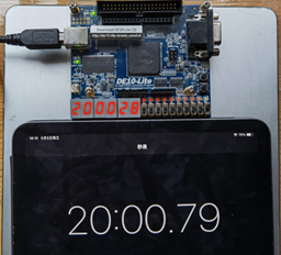
Initially, all digits are set at 0. When the user presses the Start/Stop key and the reset switch is at 1 (i.e., in the inactive position), the stopwatch starts counting. If the Hold button is pressed at this time, the counter is paused (Fig.1) and the count continues when the button is unpressed. When the user presses the Start/Stop key again, the stopwatch ends. At this point, if the reset switch is set to 0, the count is cleared, and the screen displays the initial full 0 digits (Fig.2). When implementing this, note that if the Hold button is pressed, the stopwatch should pause; as the user releases the button, the stopwatch continues.
This coursework is a continuation of the Principles of Digital Circuits course (XJEL1620), where we should complete basic programmable logic designs on FPGA development boards using basic digital logic components, including but not limited to Multiplexer, D-type Flip-flop, Clock Divider, etc. Also, we should know how to design the testbench (both the traversal test and the constrained random test) and verify the codes or designs using the built-in simulation software before downloading to the development board. This assignment allows us to complete the design-develop-debug-test-deployment, a whole process of development.
 |
 |
| Fig.1 The counter result was precise, 20:00:28. | Fig.2 The digits were reset to 0, see switch at 0 state in red box. |
Seven Segment Encoder module
First, I read the coursework description file and learned that the file “SevenSegEncoder” is supposed to convert values that have been divided by minutes, seconds, and ten milliseconds into 8-bit data format for 7-segment displays.
I didn't know how to use “BCDEncoder” at first, but by looking at the input and output format of this file, I understood that an eight-bit value should be input (equal to a 3-bit decimal value) and the output should be 12-bit, with 4 bits representing a number on a digit (e.g. 0-3 bits representing a single digit value). Then I need to complete the minutes, seconds, and ten milliseconds clock values to 8 bits (by adding 1-bit zeros).
Next, each 4-bit of the “BCDOut” is assigned to the corresponding register, each represents a single decimal value should be displayed.
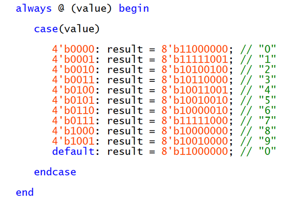
Finally, I need to know how to convert these 4-bit binary (1-bit decimal) to the format displaying on 7-segement display. By referring to the board documentation, I made following converter:
And the “result” represents the value should be assigned to i.e. “hex_hundredths”, and so on.
Stopwatch Logic module
Inside this module, there are controller codes, a number counter, a “getMinute” module, a “getSecond” module, and a “getDecs” module.
-
Controller logic: These three “always” blocks refer to three functions: Start/Stop- if the reset is 1, not in pause state, then invert Start/Stop state; Hold- if the counter is running, and the reset is 1, then pause or resume the counter when pressing or off-pressing; Overflow- if counter’s count reaches the maximum, then overflow LED is on, otherwise off.
-
Counter: When reset switch is 0, the count is reset to 0; when the counter is start, and it is not in the pause state, the counter pluses 1; otherwise it stays at its current number, or when reaches the maximum, it is fixed at 599999 (99mins: 59 secs: 99 decs).
-
getMinute/getSecond/getMillisecs: Get the number of minutes, seconds, and decimal milliseconds contained in the decimal number count, according to the modulo operation of mathematics.
Since the number of combinations of all possible conditions is 100 * 60 * 100 = 600,000, which is a very big value. The reason for testing this module is to know if the 7-segment displays can show the digits correctly. Hence, there’s no need to verify the whole combinations, as long as the number 0-9 are tested, the result is reasonable.
I created three “for” loops, each represents the minutes, seconds, or milliseconds, and the range for iterator is from 0 to 20. Any machine could simulate these 8000 combinations very quickly.
The partial results are shown below, which indicate the correctness of this module.
After calculation, to verify that the timer is logically correct for each case, it would require traversing close to 600,000 values one by one, which is considered an unacceptable time overhead in simulation. So I introduced a constrained random test schedule: within a controlled short time (here I took 1000-10000 time units to simulate realistic 1s-10s timing), randomly generate timing intervals and randomly add whether the Hold button is pressed or not, and finally judge whether the output of the module is consistent with the theoretical calculation; repeat the test 50 times.
First, to test the accuracy of timer, I set two random “testtimes”. In each for loop, all parameters are set to their initial state (1 for active). Then the timer starts, the testing codes stop for those two random time intervals to let the timer run for such the time. It will be random if the timer should be held for another time interval. Finally, by comparing the “testresult” and module outputs, the result can be verified. And all parameters are reset. (Start/Stop, Hold, Reset, timer counting results are all tested)
Second, to test if the timer is overflow, a very long time interval 1,200,000 is set (twice the maximum threshold 99:59:99, since here for 1 time unit the clock signal is inverted, the clock frequency is not 100Hz but 50Hz. It’s not convenient to set #0.5, so I just leave #1 there). After this time, the timer should be overflowed, and the result “stopwatch_overflow” can be tested.
Within the codes above, see the output below: all 50 normal timer tests passed, and the final overflow test also passed. The module can be regarded as correct.


