This is an Audio Sampler and (maybe) a Syntheziser project created for the Digilent Zybo board. The idea is to recreate the audio engine of the Keyboard Workstations of the mid-late 2000's (like the Fantom X series from Roland) to create an open source Hardware sampler powerful enough to recreate any sound from the last decade... Let's see if this FPGA can do it.
I am basing this design on the architectures used in Roland and Korg keyboard, where the CPU is used to handle basic tasks like managing the display, lights, buttons, etc. and a dedicated sound engine is used to load the samples and perform DSP. From the processor speed and memory perspective, this board and FPGA should outperform the hardware present in those keyboards. However it is difficult to tell if the same will be true for the DSP and DMA capabilities present in those keyboards ASICs. Note that the idea is to end up with a user-friendly UI with a display and buttons and knobs and whatnot.

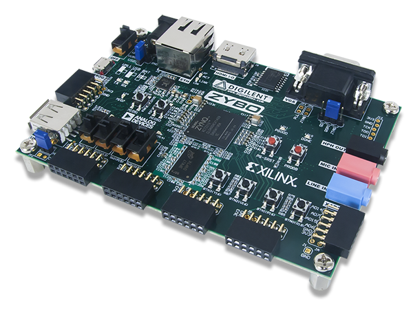
Note that this Zybo board has been discontinued and replaced by the Zybo Z7-10 and the Z7-20. The upgrades include more ram, faster clocks, a MIPI connector, a second HDMI port and (in the case of the Z7-20) a larger FPGA. This project will continue targeting the old Zybo because I'm not a Rockefeller.
You can find more about the board over at https://reference.digilentinc.com/reference/programmable-logic/zybo/start
[DONE] Created the git repo
[DONE] CODEC control module (I2C)
[DONE] AXI Registers module
[DONE] Basic FW Interface to the RTL registers
[DONE] Basic interrupt handler mechanism for the board buttons
[DONE] I2S Serializer + test tone
[DONE] I2S HW Control Registers
[DONE] DMA Interface between the ARM core and the I2S controller
[DONE] FW Test Sine Wave Tone Generator (Using DDS)
[DONE] FreeRTOS CLI Interface over UART to the PS
[DONE] Enable FreeRTOS+FAT to access the SD card
[DONE*] Custom DMA engine to support up to 64 different DMA regions (64 voices)
[DONE] Develop application to download samples to memory from an SD Card
[DONE] Enable a MIDI bridge using UART
[DONE] Increase the scalability of the DMA engine
[IN PROGRESS] Enable playback from SF2 files
[IN PROGRESS] Playback samples from an open source library
[NOT STARTED] Enable true velocity switches
[NOT STARTED] Enable attack and release envelope settings
[NOT STARTED] Enable layerd instruments
[NOT STARTED] Enable multi-library simultaneous loading
[NOT STARTED] Square Wave Synthesizer
[NOT STARTED] Sine Wave Synthesizer
[NOT STARTED] Sawtooth Wave Synthesizer
[NOT STARTED] Enable FM synthesis using preset waveforms
[NOT STARTED] Enable FM synthesis using recorded waveforms
[NOT STARTED] Enable USB stack for Host Mode
[NOT STARTED] Enable MIDI over USB
[IN PROGRESS] Enable a UVM Testbench
[NOT STARTED] Automate register generation
- Xilinx Vivado 2020.1
- Xilinx Vitis 2020.1
Before you build, you need to setup the environment. To do that, you need to run the Vivado and Vitis (previously Xilinx SDK) setup scripts like this
## From the Windows CMD shell
# Vivado
[CMD]>> call D:\Xilinx\Vivado\2020.1\settings64.bat
# Xilinx Vitis (previously Xilinx SDK)
[CMD]>> call D:\Xilinx\Vitis\2020.1\settings64.bat
## From the Linux Bash shell (TODO)
...The build process goes through the following stages
This stage will package the individual cores using the Vivado IP Packaging tool so that they can be easily integrated into the final build. You only need to re-run this stage when performing changes to the top-level IO or parameters of the individual subsystems
This stage will import all the packaged cores and, using the integration script, generate the top-level RTL files for synthesis. You only need to re-run this stage when changing the connections or the parameters of the individual subsystems
This stage will individually synthesize all Xilinx IPs to save time on the final implementation. Note that this stage is only strictly necessary when you haven't created the Xilinx IPs from the TCL scripts. Xilinx IPs instantiated in the integration stage can also be synthesized in the implementation stage
This stage will import the generated sources from the integration stage and will perform Synthesis and Place and Route
This stage will create a Vitis workspace and configure the BSP and the Project application. Note that you will still need to open the Vitis GUI to compile the firmware and program the board
This stage only performs a simple compile to check for syntax errors. To run this stage you need to have passed at least stage 3)
This stage is still work in progress. This stage will run the UVM testcase of a given testbench. To run this stage you need to have passed at least stage 3)
To build the project, you need to run one script using Vivado: run.tcl.
## Run the complete build flow from scratch
>> vivado -mode batch -source scripts/run.tcl -tclargs -cfg cfg/zybo_sampler.cfg.json

## Run only specific stages
# Stages: PACK | INTEG | GEN_XILINX_IP | IMPL | BUILD_WS | LINT (optional)
>> vivado -mode batch -source scripts/run.tcl -tclargs -cfg cfg/zybo_sampler.cfg.json -stages "<STAGE1>+<STAGE2>+..."
# Example
>> vivado -mode batch -source scripts/run.tcl -tclargs -cfg cfg/zybo_sampler.cfg.json -stages "INTEG+IMPL"
>> vivado -mode tcl   -source scripts/run.tcl -tclargs -cfg cfg/zybo_sampler.cfg.json -stages "LINT"

## Run with stage arguments
>> vivado -mode batch -source scripts/run.tcl -tclargs -cfg cfg/zybo_sampler.cfg.json -stages "<STAGE1>+<STAGE2>+..." --stage_args "<STAGE1>_ARG1=1" "<STAGE2>_ARG2=MyValue" --
# Example
>> vivado -mode tcl -source scripts/run.tcl -tclargs -cfg cfg/zybo_sampler.cfg.json -stages "SIM" --stage_args "SIM_TB=codec_unit_top_tb" "SIM_TC=codec_unit_top_testcase_1" --# Note 1: This stage can also be executed from Vivado, but it will be calling this command
# Note 2: This stage will only build the Vitis Workspace.
# You will need to load Vitis to compile the firmware and program the board
# Note 3: For Vitis 2019.2, there's a Windows bug related to the Xilinx Software Command Tool (xsct)
# You may need to apply this patch: https://www.xilinx.com/support/answers/73252.html
>> xsct scripts/run.tcl -tclargs -cfg cfg/zybo_sampler.cfg.json -stages "BUILD_WS"# To run the UVM simulation, you need to use a Vivado version equal or greater than 2019.2 -- That's when they added support for UVM
# You need to provide the Testbench name and the Testcase name using "SIM_TB=<testbench>" and "SIM_TC=<testcase>"
# Right now the testbench and testcases are dummy placeholders
# Example
>> vivado -mode tcl -source scripts/run.tcl -tclargs -cfg cfg/zybo_sampler.cfg.json -stages "SIM" --stage_args "SIM_TB=codec_unit_top_tb" "SIM_TC=codec_unit_top_testcase_1" --Right now the project has very (VERY) limited functionality, but here's what you can do
To launch the project, simply power on the Zybo and go into Vitis (previously Xilinx SDK) with the compiled project. Once you're there go to Xilinx -> Program FPGA. Select the bitfile from the results/audio_sampler_integ directory and click on Program
Now that the bitfile has been downloaded, go to your Project Explorer and right click on the .elf file that is under codec_fw -> Binaries -> codec_fw.elf. On the menu, go to Run As and select Run on Hardware (System Debugger).
To interact with the CLI, open a serial terminal (using a program like PuTTY) and configure the following settings
Baud Rate: 115200Data Bits: 8Stop Bits: 1Parity: None
Once the settings have been configured, open the serial connection. You should be greeted with a screen like this one. You can type help to see the commands available.

Command
>> sd_init

Command (after sd_init)
>> dir

The sampler currently supports only one instrument at a time. Each instrument should be defined using a file in JSON format. The structure of such file is the following
The instrument name should be located in the first layer of the JSON file (preferrably at the beginning) like this
{
    "instrument_name": "My Piano Library",
    ...
}The samples related to this instrument should be defined in a second layer called "samples" like this
{
    ...
    "samples": {
        ...
    }
}
Inside this section, the samples for each note should be defined as follows
<NOTE_NAME><NOTE_NUMBER>(_S)
where:
<NOTE_NAME>Is the name of the note (A to G).<NOTE_NUMBER>Is note number (0 to 8).(_S)Is optional. It represents a "sharp" note
Example: "A4_S" is equivalent to A4#
Each has its own sub_fields, such as sample path (relative to the .json file) and minimum and maximum velocities (Note. Right now only 1 velocity range is supported, but this will be expanded for multi-sampled instruments). The field names are:
sample_fileThis points to the sample file relative to the .json filevelocity_minMinimum velocityvelocity_maxMaximum velocity
Example:
{
    ...
    "samples": {
        ...
        "C3_S": {
            "sample_file": "samples/piano_c3_sharp.wav",
            "velocity_min": 0,
            "velocity_max": 255,
        }
        ...
    }
}