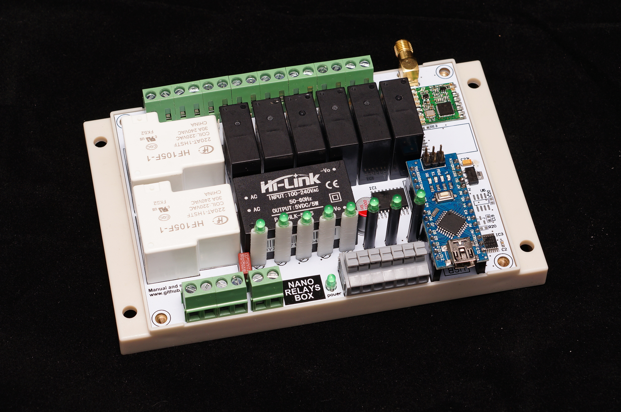
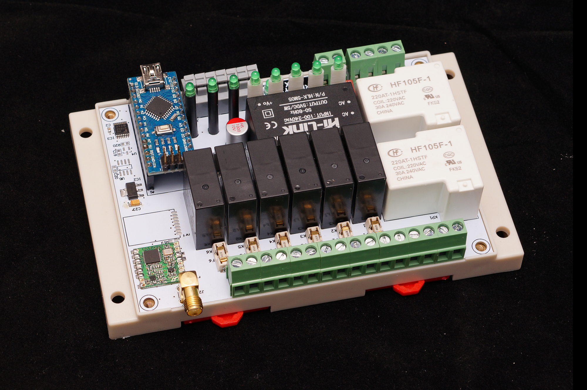
The Nano Relay Box is a low cost wireless 220 Volts 8 Relay board. Arduino Nano micro-controller with RFM 69 HW radio on board (optional NRF24L01+). Onboard 220 Volts HLK-5M05 power supply . Secure authentication with ATSHA204A crypto-authentication (optional, footprint available). Best suitable for Home Automation, IOT.
- Authentication security - Atmel ATSHA204A Crypto Authentication Chip (optional, footprint available)
- External JDEC EPROM (optional, footprint available)
- RFM69-HW (high power version) 433 - 868 - 915 MHz Radio transceiver
- NRF24L01+ (optional, footprint available)
- 2 x Power Relays capable to hold current up to 20A
- 6 x Relays capable to hold current up to 10A
- 8 LED's indicating Relay Status
- 7 pins terminal with 4 Analog GPIO, 3.3v and 5v
- Supply voltage 240 Volts AC for HLK-5M05 power supply
- Protection:
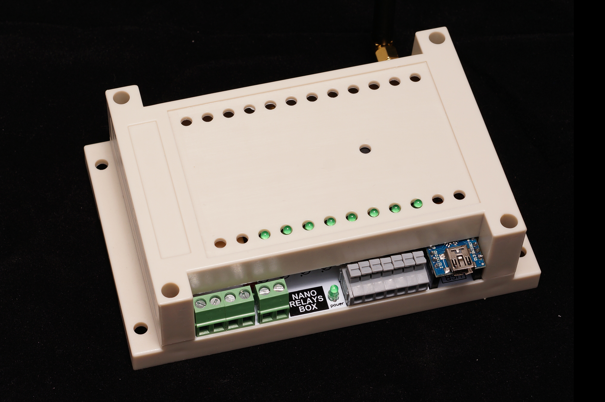
Fuses for 10A relays - Din rail plastic enclosure
- Enclosure dimensions 145x90x40
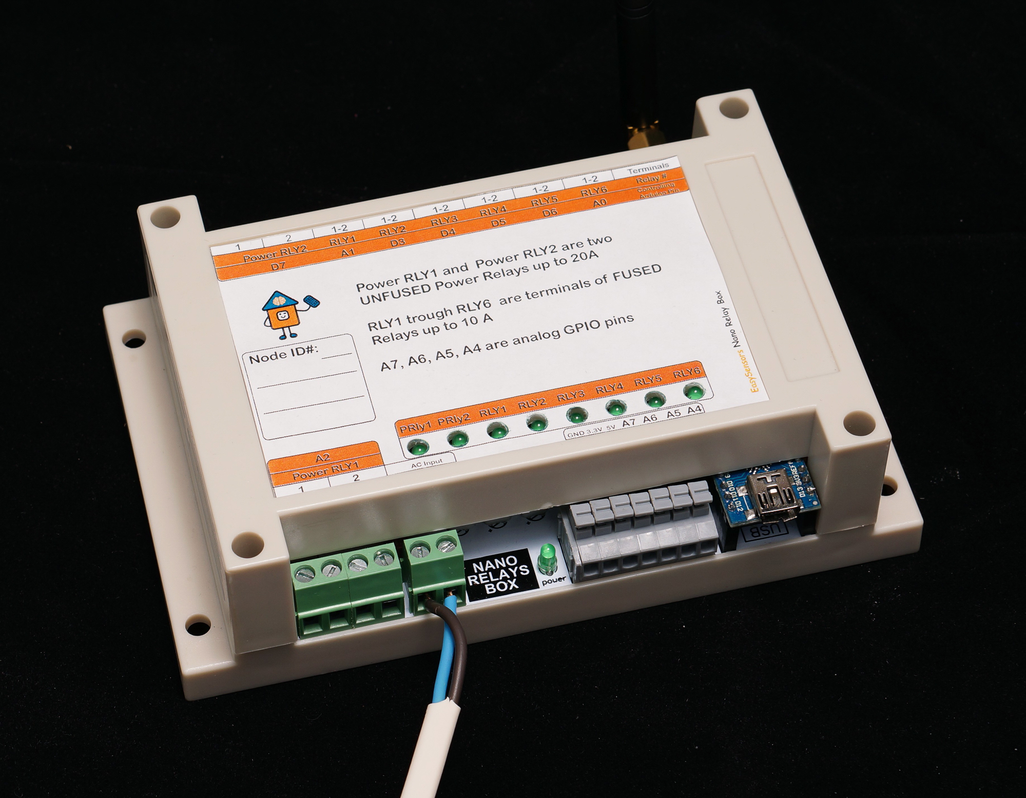
Pin out:
| Arduino Pins | Description |
|---|---|
| A2 | Controls unfused Power Relay1. Current up to 20A |
| D7 | Controls unfused Power Relay2. Current up to 20A |
| A0 | Controls fused Relay1. Current up to 10A |
| D6 | Controls fused Relay2. Current up to 10A |
| D5 | Controls fused Relay3. Current up to 10A |
| D4 | Controls fused Relay4. Current up to 10A |
| D3 | Controls fused Relay5. Current up to 10A |
| A1 | Controls fused Relay6. Current up to 10A |
| A3 | Connected to ATSHA204A footprint |
| Arduino Pins | Description |
|---|---|
| GND, 3.3V,5V, A7, A6, A5, A4 | connected to grey terminals |
nanoRelayBox.ino is the Arduino example sketch using MySensors API.
Burn the miniRelayBox.ino sketch into it and it will became one of the MySensors home automation network Relay Node. The Relay could be controlable from a smarthome controller web interface or smarphone App. To create Home Automation Network you need smarthome controller and at least two Nodes one as a Sensor, relay or actuator Node and the other one as “Gateway Serial” connected to the smarthome controller. I personally love Domoticz as home automation conroller. Please check this HowTo to install Domoticz.
However, for no-controller setup, as example, you can use 3 nodes - first node as “Gateway Serial”, second node as the Mini Relay Box node and the last one as switch for the relay node. No controller needed then, keep the switch and the relay node on the same address and the switch will operate the relay node.
Things worth mentioning about the MySensors Arduino sketch:
| Code | Description |
|---|---|
| #define MY_RADIO_RFM69 #define MY_RFM69_FREQUENCY RF69_433MHZ #define MY_IS_RFM69HW |
Define which radio we use – here is RFM 69 with frequency 433 MHZ and it is HW type – one of the most powerful RFM 69 radios. If your radio is RFM69CW - comment out line with // #define MY_IS_RFM69HW |
| #define MY_NODE_ID 0xE0 | Define Node address (0xE0 here). I prefer to use static addresses and in Hexadecimal since it is easier to identify the node address in Domoticz devices list after it will be discovered by controller ( Domoticz). However, you can use AUTO instead of the hardcoded number (like 0xE0) though. Domoticz will automatically assign node ID then. |
| #define MY_OTA_FIRMWARE_FEATURE #define MY_OTA_FLASH_JDECID 0x2020 |
Define OTA feature. OTA stands for “Over The Air firmware updates”. If your node does not utilize Sleep mode you can send new “firmware” (compiled sketch binary) by air. Here is the link on how to do it. For OTA we use JDEC Flash chip where the node stores new firmware and once it received and controlsum (CRC) is correct it reboots and flashes your new code into the node controller. So we define it is "erase type" as 0x2020 here. |
| #define MY_SIGNING_ATSHA204 #define MY_SIGNING_REQUEST_SIGNATURES |
Define if you like to use Crypto Authentication to secure your nodes from intruders or interference. After that, you have to “personalize” all the nodes, which have those, defines enabled. How to “personalize” nodes with encryption key. You need both defines in the nodes you need to protect. The Gateway Serial could be with only one of those defines enabled - #define MY_SIGNING_ATSHA204 |
Connect the Relay to FTDI USB adaptor, Select Pro Mini 8MHz board in Arduino IDE and upload the miniRelayBox.ino sketch.
Done
The board is created by Koresh