2015_sirius
![]()
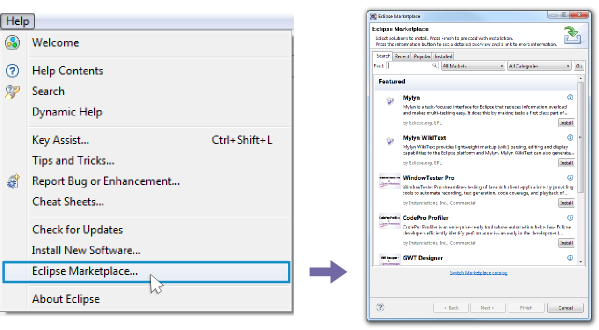
homesite: http://eclipse.org/sirius/
Install from eclipse market place: search for Sirius -> Click Install -> etc.
- Import the original metamodel projects from here.
- (Generate *.edit and *.editor from the appropriate *.genmodel file in the model folder.)
- Run as Eclipse Application.
- Import the project from here to the runtime Eclipse and check the instance model.
- We will work in Runtime Eclipse
In the Runtime Eclipse
-
Create a new Viewpoint Specification Project and name it as _hu.bme.mit.mdsd.erdiagram.design while the Viewpoint specification model would be called erdiagram.odesign. Note: this is a Sirius related project type to describe a Sirius editor
-
Switch to Modeling perspective Note: Window -> Open perspective -> Other... -> Modeling
-
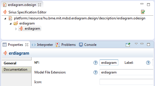
In odesign editor, add a new view point: right click on the viewpoint (in the editor) -> New -> Viewpoint. Set its Model File Extension property to "erdiagram".
-
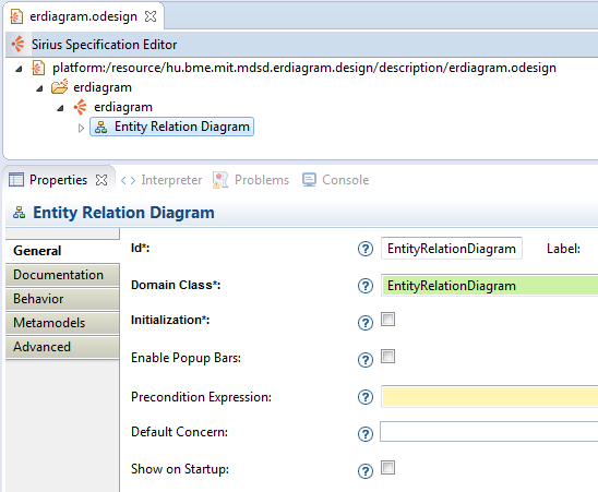
Under the viewpoint, create a diagram representation (right click on the viewpoint -> New Representation -> New Diagram Representation) and set its domain class to our root metamodel class: EntityRelationDiagram.
-
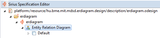
Create a default layer under the diagram representation (right click on the representation -> New Diagram Element -> Default Layer).
Under the default layer:
-
Create a Node typed diagram element (right click on the layer -> New Diagram Element -> Node) and set its domain class to Entity and its semantic candidates expression to feature:entities. Note: the Semantic Candidate Expression describes the navigation path from the parent domain class to the selected ones. In this the parent is EntityRelationDiagram and we select all the object on its entities reference. Note: the feature: selects a structural feature (attribute or reference) from a domain class
-
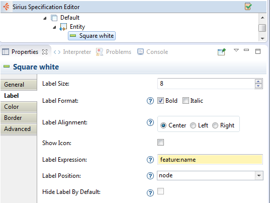
Define a style for the Node (right click on the Node -> New Style -> Square). You can change its properties if you want.
-
Create a Node typed diagram element and set its domain class to Attribute and set its semantic candidate expression to [self.entities.attributes->addAll(self.temporary->filter(Attribute))/] Note: inside the squre brackets you can acceleo expressions - acceleo
-
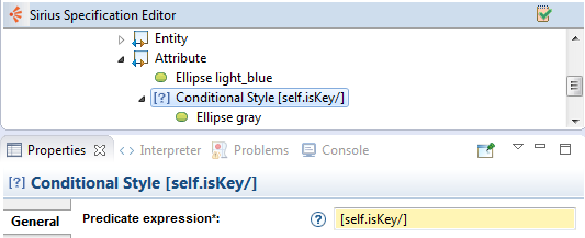
Create styles and conditional styles for attributes based on the isKey properties. The condition will be the following: [self.isKey/] Note: A default style is alway required. Note: Create Conditional Style - right click on the Node -> New Conditional Style -> Conditional Style and then you can create a new style under the conditional style element. Note: Do not forget to fill the predicate expression in the conditional style. Note: If the predicate expression is true the conditional style will be applied.
Under the default layer:
-
Display connections between an entity and its attributes
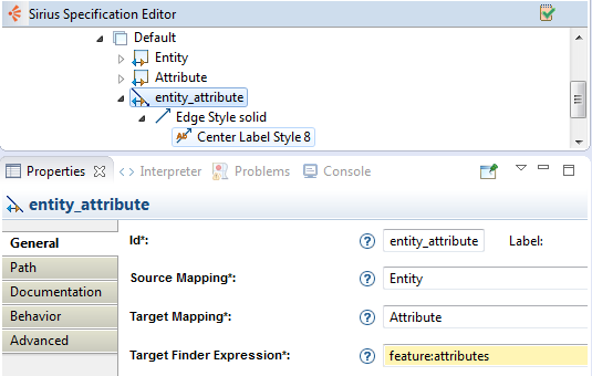
- Create a Relation Based Edge typed diagram element (right click on the layer -> New Diagram Element -> Relation Based Edge).
- Set its source mapping to Entity (defined previous)
- Set its target mapping to Attribute (defined also previous)
- Set its target finder expression to "feature:attributes" Note: the target finder expression is related to the source mapped objects
- By default, a simple edge style is create which is good for us now, but you can check its properties.
-
Display connections between entities based on the relation objects
- Create an Element Based Edge typed diagram element (right click on the layer -> New Diagram Element -> Element Based Edge).
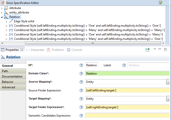
- Set its domain class to Relation
- Set its source mapping to Entity (defined previous)
- Set its source finder expression to "[self.leftEnding.target/]"
- Set its target mapping to Entity (defined also previous)
- Set its source finder expression to "[self.rightEnding.target/]"
- We left the semantic candidates expression empty, but we should fill it with "feature:relations" Note: for the proper functioning, this is not required but recommended
- By default, a simple style is provided for the edge, but define additional conditional styles based on the multiplicity of a relation:
- [self.leftEnding.multiplicity.toString() = 'One' and self.leftEnding.multiplicity.toString() = 'One'/]
- [self.leftEnding.multiplicity.toString() = 'Many' and self.leftEnding.multiplicity.toString() = 'One'/]
- [self.leftEnding.multiplicity.toString() = 'One' and self.leftEnding.multiplicity.toString() = 'Many'/]
- [self.leftEnding.multiplicity.toString() = 'Many' and self.leftEnding.multiplicity.toString() = 'Many'/]
- Change the ending of the edges alse based the multiplicity (inside properties of an edge style, check the decorators tab)
Under the Section (create one, if you don't have: right click on the layer -> New Tool -> Section)
-
Create Entities
- Add a Node Creation (right click on Section -> New Element Creation -> Node Creation)
- Under the green arrow with the begin label, we can define an operation sequence to be executed.
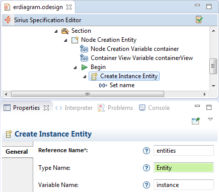
- Create a new instance operation (right click on Begin -> New Operation -> Create Instance)
- Set its reference name to "entities" Note: without any prefix, only the reference name _Note: field is related to the domain class of the diagram (or the container node) where we add the new instance
- Set its type name to Entity, as we want to create a new Entity
- Set its variable name to "instance" _Note: we won't use this feature, but with its name, you can refer to this object later (var:)
- Under the new instance operation, create a Set operation (right click on Create Instance Entity -> New Operation -> Set)
- Set its feature name to "name"
- Set its value to "undefined" Note: this will set the name attribute of the new object to "undefined" by default
-
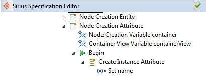
Create Attributes
- Add a Node Creation (right click on Section -> New Element Creation -> Node Creation)
- Under the green arrow with the begin label, define the operation sequence.
-
Create a new instance operation (right click on Begin -> New Operation -> Create Instance)
-
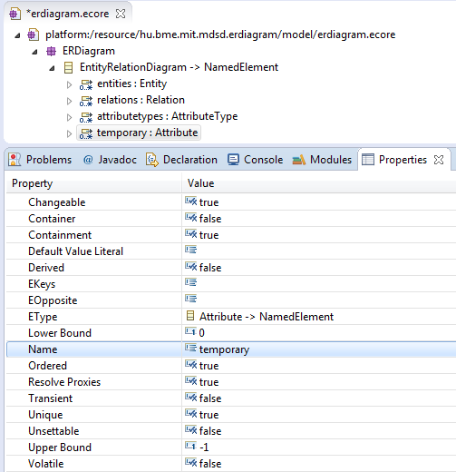
Despite the fact, that our EntityRelationDiagram class cannot contain Attribute typed objects in any of its features, we have to extend the metamodel.
- Stop the RuntimeEclipse.
- Open the erdiagram.ecore file.
- Add a new reference to EntityRelationDiagram
- Name: temporary
- Type: Attribute
- Multiplicity: many (0..*)
- Save the metamodel
- Reload it in the genmodel.
- Regenerate the model, edit and editor code from the genmodel
- Start the Runtime Eclipse again.
-
Set its reference name to "temporary"
-
Set its type name to Attribute
-
Set its variable name to "instance"
-
- Under the new instance operation, create a Set operation (right click on Create Instance Entity -> New Operation -> Set)
- Set its feature name to "name"
- Set its value to "undefined"
Under the Section (create one, if you don't have: right click on the layer -> New Tool -> Section)
-
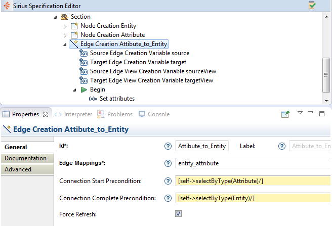
Create edge between Entity and Attribute
- Add a Edge Creation (right click on Section -> New Element Creation -> Edge Creation)
- Set its edge mapping to "entity_attribute" Note: this is the edge element that we defined previous (Visualizing edges/1st step)
- Set its connection start precondition to [self->selectByType(Attribute)/] _Note: this acceleo expression will select all attribute typed objects
- Set its connection end precondition to [self->selectByType(Entity)/] Note: these two precondition will restrict the editor to disable undesirable edges
- Add a Set operation under the Begin element
- Feature name: "attributes" Note: related to the source object
- Value expression: "target" Note: this is a variable created automatically and refers to the selected target object
-
Create edge between Entities (using Java Code)
-
Add a Edge Creation (right click on Section -> New Element Creation -> Edge Creation)
-
Set its edge mapping to "Relation" Note: this is the edge element that we defined previous (Visualizing edges/2nd step)
-
Set its connection start precondition to [self->selectByType(Entity)/]
-
Set its connection end precondition to [self->selectByType(Entity)/]
-
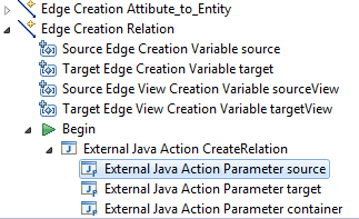
Add an External Java Action operation under the Begin element (right click on the Begin element -> New Extension -> External Java Action)
- Set its Java Action Id to "CreateRelation"
- Add parameters: source, target, container (right click on the External Java Action -> New -> External Java Action Parameter)
- Set their properties:
- name: source, value var:source
- name: target, value var:target
- name: container, value var:container
- Set their properties:
-
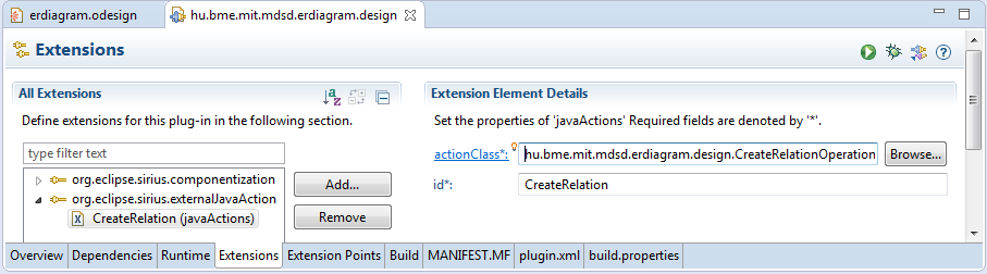
Open the plugin.xml of the project
-
Switch to the extensions tab
-
Add a new extension: org.eclipse.sirius.externalJavaAction
-
Add a new java action under the extension
-
Set its id to "CreateRelation" (same as Java Action Id!)
-
Create an action class: CreateRelationOperation
'''java public class CreateRelationOperation implements IExternalJavaAction {
@Override public void execute(Collection<? extends EObject> selections, Map<String, Object> parameters) {
   Entity source = (Entity) parameters.get("source");
   Entity target = (Entity) parameters.get("target");
   EntityRelationDiagram diagram = (EntityRelationDiagram) parameters.get("container");

   Relation relation = ERDiagramFactory.eINSTANCE.createRelation();

   RelationEnding leftRelationEnding = ERDiagramFactory.eINSTANCE.createRelationEnding();
   RelationEnding rightRelationEnding = ERDiagramFactory.eINSTANCE.createRelationEnding();

   relation.setLeftEnding(leftRelationEnding);
   relation.setRightEnding(rightRelationEnding);

   leftRelationEnding.setTarget(source);
   rightRelationEnding.setTarget(target);

   leftRelationEnding.setName("undefined");
   rightRelationEnding.setName("undefined");

   diagram.getRelations().add(relation);
}
@Override public boolean canExecute(Collection<? extends EObject> selections) { for (EObject eObject : selections) { if(!(eObject instanceof Entity)) { return false; } } return true; }
} ''' Note: the added parameters can be reached in the "parameters" map
-
Create new validation for our diagram (right click on diagram element -> New Validation -> Validation)
-
Create a new Semantic validation (right click on validation element -> New -> Semantic Validation)
-
Set its level to "Information"
-
Target class: "Attribute"
-
Message: "Hi! I'm an Address." Note: this describes what will happen when our model has a problem
-
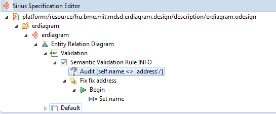
Create an Audit under the semantic validation (right click semantic validation -> new -> audit)
- Set its audit expression to "[self.name <> 'address'/]" Note: this describes whether our model is correct or not. If the expression returns false, the element is incorrect.
-
Create an Quick Fix under the semantic validation (right click semantic validation -> new -> quick fix)
- Create a Set operation under the Begin element
_Note: this is also an operation sequence to be executed when someone click on the quick fix
- feature: "name", value: "addresss"
- Create a Set operation under the Begin element
_Note: this is also an operation sequence to be executed when someone click on the quick fix
-