2018_emf
Author: Oszkár Semeráth, András Szabolcs Nagy, Bence Graics, Gábor Bergmann
From Wikipedia (http://en.wikipedia.org/wiki/Eclipse_Modeling_Framework): ''Eclipse Modeling Framework (EMF) is an Eclipse-based modeling framework and code generation facility for building tools and other applications based on a structured data model.'' EMF's data model is lightweight as it defines only a few but well-defined modeling elements. However, it has an extensive tooling support and community. For example, you can define the textual or graphical syntax of a language and generate the appropriate editors.
EMF can generate Java code from the metamodel with only a click of a button. The generated code provides a Java object API aligned with the metamodel. Out of the box, EMF is capable of serialization to XMI and deserialization from XMI files.
EMF home page: http://www.eclipse.org/modeling/emf/
Note: Since Eclipse Luna (25. 06. 2014.), the EMF Ecore visual editor (Ecore Tools) has changed and now based on Sirius changing the extension name of the diagrams to .aird. Legacy diagrams (.ecorediag) cannot be opened with the Eclipse Luna Modeling Tools edition. You can find the home page of the Ecore Tools project along with tutorials here: https://www.eclipse.org/ecoretools/overview.html
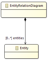
The goal of this exercise is to create the metamodel of customized Entity-Relationship Diagrams (ERD). These diagrams can aid the development of software components working with complex data structures. A later exercise will demonstrate how complete database schemes, full classes and automated mappings between those can be derived from such models.
The following figure presents an example of an Entity Relation diagram.

The Eclipse Modeling Tools edition contains every required plug-in.
-
Create a new Empty EMF Project by File | New | Other... | Eclipse Modeling Framework | Empty EMF Project. Name it
hu.bme.mit.mdsd.erdiagram. This project is a Java plugin project (has an src folder and a MAINFEST.MF file) with the required ecore dependencies. -
There is a folder in the project named model. Create a new Ecore Model in it by right-clicking on the folder and choosing | New | Other... | Eclipse Modeling Framework | Ecore Model. Name it
erdiagram.ecore. -
A new editor opens showing that the model resource has a yet unnamed empty package. Fill the missing properties in the property view, use only small case letters:
- Name:
erdiagram - Ns Prefix:
erdiagram(namespace prefix in xml) - Ns URI:
hu.bme.mit.mdsd.erdiagram(works as global ID. Another convention is to usehttp://example.com/erdiagram)
If the Properties View is not shown, right-click on the package element in the editor, and select Show Properties View. In general, to show any unavailable views go to Window | Show View or use the Quick Access box.
- Name:
-
Use this tree editor to create the first EClass that will represent the ERD root model element (right-click on the package | New Child | EClass) and name it EntityRelationDiagram in the Properties View. Do not forget to save the model. Also, try out the other context menu items.
-
While it is possible to create the model in this tree editor, there is a more convenient editor for this purpose. In order to add diagrams to the project press Right click on the project | Configure | Enable ViewModelNature.
-
Right-click on the ecore file and choose the Initialize ECore diagram... option. Name it erdiagram.aird. Click Finish. After that, choose the Design/Entities (or Entities in a Class Diagram) representation, then the package
erdiagram. Name the representation Entity Relation class diagram. -
If you choose Empty EMF Project by File | New | Other... | Eclipse Modeling Framework | Empty EMF Project, the IDE creates a project structure similar to current state.
-
Add the first element from the palette with Existing Elements | Add command, then choose the EClass we have already created. Alternatively, double click on the canvas when the diagram is first initialized. Note that the visual representation is independent of the ecore model itself, that is, deleting from the model and the diagram are different things (the latter does not necessarily result in deleting from the model).
-
Make the following part by dropping metamodel elements from the palette to the diagram:
-
If you click on a model element, you can edit its properties in the Property view.
- Specify the names of the
EClasses, theEReferences and theEAttributes. - The
EClasses can be set to Abstract or Interface in this view. - The type of an
EAttributecan be set in this view. - The multiplicity of the relation is set to
0..* - The
EOppositefeature should be presented. - The objects of the instance models of the metamodel have to be in a tree hierarchy with respect to the containment references. Set the
entitiesrelation to Is Containment. - Appearance: you can edit the view of the diagram. For example the behavior of an edge.
- Advanced Options: Direct editing for the properties of the elements of the model. The features should be presented:
- Specify the names of the
-
The effect of the diagram editing on the
.ecorefile can be observed if it is opened. It synchronizes when the diagram is saved. -
The model can be validated with the check symbol visible in the context menu (see the following figure). All of the generated markers are also listed in the Problems View.

-
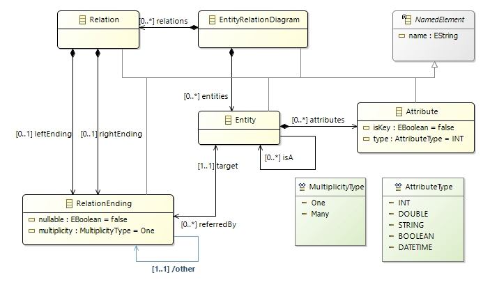
Create the metamodel of the Entity Relation Diagram on your own as if it was a class diagram. A possible result is visible in the following figure.

-
Add the
EEnumnamedMultiplicityto the metamodel, and add two literals to it:OneandMany. -
Add an abstract
NamedElementclass to the metamodel and add inheritance relations to all the EClasses. Note: the difference between theEAttributeandEReferenceis that the EAttribute refers to anEDataTypesopposed toEReferencesthat refer toEClasses. -
Add EAttributes to the classes and also create an AttributeType enumeration. The final model should be similar to the one visible in the following figure:
-
The metamodel does not contain
EOperations, because in this task our goal is to define a data model. It is important to note that the creator of EMF doesn't recommend the usage ofEOperationseither.
This example demonstrates how to generate classes and an editor from Ecore models.
-
The ecore files are the blueprints of the domain-specific languages. To use the tooling support available in Eclipse, Java class representations of those "boxes" are needed. Fortunately, such classes can be automatically generated.
Right-click on the ecore file and select New | Other | Eclipse Modeling Framework | EMF Generator Model. The default
erdiagram.genmodelis fine. In the next step, choose that the generator should generate from an Ecore model. In the third step, the URI of the Ecore model has to be specified. Click on load and next. Choose the only available package to generate and hit finish. -
As a result, another tree editor (similar to the ecore editor) opens. Browse some of the settings in the property editor. Right-click on the root, and choose the Generate Model command. Three packages are generated in the source folder. The first one contains the Classes we created in the form of Java interfaces. Moreover, there are two special interfaces: *Factory.java and *Package.java, we will get back to these later. Browse for example the
hu.bme.mit.mdsd.erdiagram/src/erdiagram/EntityRelationDiagram.javafile, and you can see that nothing strange has been generated, it is an interface with basic methods. The second package (erdiagram.impl) contains the implementation classes. The implementation class has some unusual fields, but the implementations of the interface functions are quite simple. The erdiagram.util package contains two helper classes, which can be useful in advanced scenarios. -
The main function of the generator model is to control the generated code. For example, we notice that the generated package names, unfortunately, do not match the project name. To correct this, click on the Package element and find All | Base Package. Change it to
hu.bme.mit.mdsd. This will correct the generated package names according to the project name. Regenerate the Model code, delete the previously generated code and correct the MANIFEST file as it tries to export the deleted packages. Also, you could change the name of thesrcfolder (for example toemf-gen). For that, click on the root object on the .genmodel editor and find Model | Model Directory and then change thesrcfolder toemf-gen. However, this will break the generated tree editor in the runtime Eclipse, so do not do this now. Further options in the generator model include e.g., selecting a label feature for each class (e.g., "name"). -
If you change the ecore model, you have to reload the generator model by Right-click | Reload... Changes to the generator model file will be preserved. Note that in some cases, this reload procedure does not overwrite the code generation settings for certain model elements (as ecore aims to support the manual customization of these settings). For example, if you set the
Containmentattribute of anEReferenceto true from false in the ecore model, or vice versa, the corresponding setting in the generator model does not change automatically even after the reload of the generator model. Try this by setting theContainmentattribute of the leftEndingEReferenceto false. Check out the properties of the leftEndingEReferencein the generator model (Erdiagram | Relation | leftEnding in the generator model tree editor). Open the Edit view and note that theChildrenandCreate Childattributes are still set to true, which can cause unexpected problems, for example, when using the generated editor. If you want the generator model to stay consistent with the ecore model, you can edit these properties manually after such changes, or delete and create a new generator model based on the ecore model. -
Generate an editor. Right-click on the root of the genmodel file, and generate edit and editor in this order.
-
Right-click on the project, and choose Run as | Eclipse application. Alternatively, select from the toolbar Run | Run configurations...| Eclipse application, then hit the New launch configuration button, optionally fill out parameters (such as launch configuration name), and press "Run". Both options will, by default, run an "Eclipse Application" launch configuration, consisting of all plug-ins defined in workspace source projects (i.e., the plug-ins we have just generated) as well as the target platform (the latter is, by default, the set of plug-in of the Eclipse instance used for developing the plug-ins).
-
Create an empty project by File | New | Other... | General | Project and name it hu.bme.mit.mdsd.erdiagram.examplediagrams.
-
Create a new Entity Relation Diagram into the new project by right-clicking on it and selecting New | Other | Example EMF Model Creation Wizard | Erdiagram Model. The name can be the default
My.erdiagram, and the model object (what we want to edit) should be Entity Relation Diagram. -
Create the instance model. The editor is quite self-explanatory to use and very similar to the ecore tree editor.

The following example demonstrates how to edit the model from code.
-
Create a new Plug-in Project by right click | New | Plug-in Project. Name it to
hu.bme.mit.mdsd.erdiagram.example, then add the following dependencies:hu.bme.mit.mdsd.erdiagram The plug-in project's name that holds the ecore model. org.eclipse.emf.ecore.xmi The instance model is serialized as an XMI document. -
Create a class to the source folder:
package hu.bme.mit.mdsd.erdiagram.example name ErdiagramModels -
Create a model using the generated Java code. The objects of the instance model should be instantiated by the generated *Factory singleton and edited only through their interface without using the *Impl classes. The following method creates a single entity named Person with an attribute Nickname:
public EntityRelationDiagram createModel() {

    ErdiagramFactory factory = ErdiagramFactory.eINSTANCE;
    EntityRelationDiagram diagram = factory.createEntityRelationDiagram();

    Entity person = factory.createEntity();
    person.setName("Person");

    Attribute name = factory.createAttribute();
    name.setName("Nickname");
    name.setType(AttributeType.STRING);

    person.getAttributes().add(name);
    diagram.getEntities().add(person);

    return diagram;
}
-
Create a method, which traverses the model and prints out the name of the entities.
The result can be printed to the output by this method:
public void printErdiagram(EntityRelationDiagram erdiagram)
{
    for (Entity entity : erdiagram.getEntities()) {
        System.out.println(entity.getName());
    }
}
-
Create a main method that runs the previous code. Try it out by right-clicking on the class and choosing Run as | Java Application.
public static void main(String[] args) {
    ErdiagramModels erdiagramModels = new ErdiagramModels();
    EntityRelationDiagram model = erdiagramModels.createModel();
    erdiagramModels.printErdiagram(model);
}
-
Probably it will not run. Ecore models needs initialization, which can be done with the following code. Note that this is not needed if you run the code as an Eclipse application or as a JUnit Plug-in test.
public void init() {
   // For the initialisation of the model.
   // Without this the following error happens:
   //   "Package with uri 'hu.bme.mit.mdsd.erdiagram' not found."
   ErdiagramPackage.eINSTANCE.eClass();
}
-
The model can be serialized into and loaded from an xmi file, which is handled as a
Resource. A resource can be referenced by anURI(note that are a lot of classes named asURI; the one we need is in theorg.eclipse.emf.common.utilpackage). AResourceSetmanages a set ofResources. Write a method that creates and one that loads a resource with a specifiedURI:public Resource createResource(URI uri) { ResourceSet resSet = new ResourceSetImpl(); Resource resource = resSet.createResource(uri); return resource; }
public Resource loadResource(URI uri) {
    ResourceSet resSet = new ResourceSetImpl();
    Resource resource = resSet.getResource(uri, true);
    return resource;
}
-
The resource can be serialized by the
save()method:public void saveResource(Resource resource) { try { resource.save(Collections.EMPTY_MAP); } catch (IOException e) { System.out.println("The following error occurred during saving the resource: " + e.getMessage()); } }
-
The model can be retrieved from a
Resourceby thegetContents()method:public EntityRelationDiagram getModelFromResource(Resource resource) { // check the content in production code! EntityRelationDiagram root = (EntityRelationDiagram) resource.getContents().get(0); return root; }
-
Put these together in a Java main method. Note that you can get the URI by right click | Properties.
public static void main(String[] args) {
    // init
    ErdiagramModels erdiagramModels = new ErdiagramModels();
    erdiagramModels.init();
    // create
    EntityRelationDiagram model = erdiagramModels.createModel();
    // save
    URI uri = URI.createFileURI("C:/Users/meres/Desktop/samplemodel.erdiagram");
    Resource resource = erdiagramModels.createResource(uri);
    resource.getContents().add(model);
    erdiagramModels.saveResource(resource);
    // load to a different resource
    Resource resource2 = erdiagramModels.loadResource(uri);
    EntityRelationDiagram model2 = erdiagramModels.getModelFromResource(resource2);
    // print
    erdiagramModels.printErdiagram(model2);
}
Right-click on the class and choose Run as | Java Application. This will run our code as a simple Java application that creates, saves, loads and prints a model.
-
Some initialization code, which registers an xmi serializer to the given file extension, is still missing.
public void init() {
   // ...

   // Defining that the files with the .erdiagram extension should be parsed as an xmi.
   Resource.Factory.Registry reg = Resource.Factory.Registry.INSTANCE;
   reg.getExtensionToFactoryMap().put("erdiagram", new XMIResourceFactoryImpl());
}
-
After running the application again, you can find the newly created .erdiagram file in the specified path (desktop or if you specified the project folder, you may have to refresh it by pressing F5 or by the refresh button). It cannot be opened with the generated tree editor as this editor is not installed in this Eclipse. To open it, you may either use the Sample Reflective Ecore Editor, start a runtime Eclipse or install the plugins to the host by exporting it.
Above, we have created a plain Java console application that loaded, manipulated and saved EMF models. The most common scenario for handling EMF objects, however, is within the Eclipse Workbench, interacting with EMF models loaded in Eclipse editors. Although Eclipse plug-in development would deserve a course of its own, here we do a quick and rough walkthrough of contributing a context menu action to existing EMF editors that would access and modify the model under edit.
The example plug-in will register a context menu action that can be activated on any selected Entity model element, and when executed, will add an attribute named "FooBar" to the selected entity.
-
We are going to create an Eclipse plug-in project. Select File | New | Project... | Plug-in project, use a project name such as
hu.bme.mit.mdsd.erdiagram.action, and on the final page of the wizard, unclick "Create a plug-in using one of the templates". Open the fileMETA-INF/MANIFEST.MFwithin the resulting project, and add as plug-in dependencies both the model projecthu.bme.mit.mdsd.erdiagram(containing the metamodel and the generated Java classes) as well asorg.eclipse.ui(to which we will make contributions). Such dependencies can be added easily on the "Dependencies" tab (specifically the "Required Plug-ins" panel) of the manifest editor, or manually using the textual syntax on the MANIFEST.MF tab. -
Understand that there are three kinds of extensions that we must contribute to the Eclipse UI. First, we will define the "Add FooBar" Eclipse command. Second, such a command can appear on the UI in several places; it can be bound to keyboard shortcuts, shown in the main menu, on toolbars, etc.; we will specifically make a popup menu contribution so that it will (conditionally) appear in context menus. Finally, there can be multiple pieces of code called handlers that actually perform the duties of the command, one of which is always selected depending on the context; here we will register a single handler, a single way to execute the command regardless of circumstances.
-
This is achieved by contributing to three extension points provided by the plug-in
org.eclipse.ui, namelyorg.eclipse.ui.menus,org.eclipse.ui.commandsandorg.eclipse.ui.handlers. The manifest editor has an "Extensions" tab where you can add these extensions; add an extension now to, say,org.eclipse.ui.handlers(without filling out the details or creating child elements), and save the editor. -
A
plugin.xmlfile will appear, which encodes the extensions contributed by our plugin. As an alternative to the "Extensions" tab, it can be directly edited in XML syntax through the "plugin.xml" tab of the same manifest editor. Do just that, and paste the following contents. Note that the Java classhu.bme.mit.mdsd.erdiagram.Entityis referenced by its fully qualified name (as a plain string); please make sure that the name matches the one used in your workspace.<?xml version="1.0" encoding="UTF-8"?> <?eclipse version="3.4"?> <plugin> <extension point="org.eclipse.ui.commands"> <command description="Add an attribute called 'FooBar' to selected Entity" id="hu.bme.mit.mdsd.erdiagram.action.AddFooBar" name="Add FooBar Attribute"> </command> </extension> <extension point="org.eclipse.ui.handlers"> <handler class="hu.bme.mit.mdsd.erdiagram.action.AddFooBarHandler" commandId="hu.bme.mit.mdsd.erdiagram.action.AddFooBar"> </handler> </extension> <extension point="org.eclipse.ui.menus"> <menuContribution locationURI="popup:org.eclipse.ui.popup.any?after=additions"> <command commandId="hu.bme.mit.mdsd.erdiagram.action.AddFooBar" style="push" tooltip="Add FooBar Attribute"> <visibleWhen checkEnabled="false"> <with variable="activeMenuSelection"> <iterate> <adapt type="hu.bme.mit.mdsd.erdiagram.Entity"> </adapt> </iterate> </with> </visibleWhen> </command> </menuContribution> </extension> </plugin>
-
As seen above, the extension contribution has a visibility condition that makes sure that the menu item will appear only in the context menu of entities. More precisely, this will work in any view or editor (such as the default generated EMF tree editor, or the Outline view) where the selection is recognized to correspond to an Entity object. Beware that in certain concrete syntax frameworks, the selection might contain a notation element distinct from the underlying domain model EObject; in those cases, an extra wrapping/unwrapping step is needed that is specific to the given concrete syntax editor technology.
-
One could further personalize the contributions (e.g., make sure that the command is also disabled if another element is selected; make sure that the menu item will show up in the proper place within the context menu, etc.), but instead we will move over. After saving the plugin.xml, note that an warning marked is found towards the top, on the
class=line of the handler contribution. Here we reference the class implementing the handler logic, but we have not created that class yet. By moving the cursor to that line and hitting Ctrl+1, a selection of quick fixes are shown, among which we will need "Create...". Choosing that fix will pop up a "New Java Class" wizard. The interface nameIHandleris pre-filled, but we will have an easier time if we add the base classorg.eclipse.core.commands.AbstractHandler(in the "Superclass" field) as well. That way, only a single method will have to be implemented. Hit Finish. -
Note that in an Eclipse environment, the extension-point mechanism is also used to register Ecore packages in a global registry, associate file extensions with EMF resource types, etc. Thus, there is no need in this case for the previously described steps of initializing Ecore packages and registering XMIResourceImpl for the file extension; we can directly use EMF types. First, however, we have to unpack EMF object from the data structures of the selection mechanism provided by the Eclipse UI. Insert therefore the following implementation of the
AddFooBarHandler.executemethod:@Override public Object execute(ExecutionEvent event) throws ExecutionException { // unpack selected object IStructuredSelection selection = (IStructuredSelection) HandlerUtil.getCurrentSelection(event); Object firstElement = selection.getFirstElement(); // cast to Entity, which it must be in this case Entity entity = (Entity) firstElement; // perform business logic Attribute newAttribute = ErdiagramFactory.eINSTANCE.createAttribute(); newAttribute.setName("FooBar"); entity.getAttributes().add(newAttribute); return null; }
-
Once again, run an "Eclipse Application" launch configuration, consisting of all plug-ins defined in workspace source projects as well as the target platform; you can simply reuse the previous "Eclipse Application" launch config from the dropdown of the Run toolbar button. In the workspace of the runtime Eclipse, either create a new ER Diagram instance model using the wizard, or open an existing instance model file created above. Observe how "Add FooBar Attribute" will appear in the context menu of any Entity selected in either the tree editor or the outline view, and that invoking this action will indeed add a new Attribute to the model.
-
(Advanced topic) Note that even though the implemented action correctly modifies the EMF model, the change might not have marked the editor as dirty (i.e. ready for a save action), and it does not show up in the undo/redo stack either. So while using this low-level EMF model API is perfect for model transformations that take model files as input and output and manage model resources themselves, it does not play well together with models loaded and managed by an open editor. A possible solution would be to formulate changes using the EMF Command API which handles undo/redo and dirtying, and communicate these changes through the editing domain of the editor. Unfortunately, as demonstrated in the lab seminar, the basic Command API is quite difficult to manually use, especially for non-transactional editing domains. We will see a more user-friendly solution during the Viatra M2M lab session.
- If anything goes wrong with the regeneration and there is a problem with your code, you have two options:
- If the document was not edited by hand or it isn't valuable, delete it. Generate the code again, and it should be fine. It works on the
Manifest.MFand theplugin.xmltoo. - In other cases, do not be afraid of rewriting. For example, if you delete an item from the metamodel, the XMI that contains the instance model might have remaining tags with undefined types. That makes the XMI invalid, but it isn't necessary to start over the instance model; simply delete the unwanted parts from the code by hand.
- If the document was not edited by hand or it isn't valuable, delete it. Generate the code again, and it should be fine. It works on the
You can find the final state of the projects in this repository by checking out the EMF branch.
-
To demonstrate cross-resource references, create a new Erdiagram model file
other.erdiagramusing the wizard as above. Fill it with at least one entity called "Foreign Entity". Save the file, and then close the editor. -
Open the previously created
My.erdiagramin the tree editor, right-click the empty area, and select "Load resource...". Choose "Browse Workspace..." and selectother.erdiagram. Observe how the EMF Resource Set has just been expanded by an additional resource, identified by its resource URI. -
Establish a cross-reference to an EObject in the newly loaded resource by selecting a "Relation" element in the old model, and specifying "Foreign Entity" as its "right" end.
-
Save the model, close the editor, and then reopen
My.erdiagram. Observe that the second resource does not initially show up as part of the resource set. After browsing around in the tree editor, it will eventually be lazy loaded on demand, such as when the Relation pointing to the other resource (or its Properties sheet) is first shown. -
Play around with the previously created manipulation action to see how cross-resource references and lazy loading is transparent to the EMF model manipulation API.
-
Open the textual (XMI) representation of the two
.erdiagramfiles to see how the cross-reference is actually realized. Right-click on each file, select "Open With", and then "Text editor". -
As you can see, the default XMI serialization of EMF encodes cross-references as XPath expressions describing a path through the containment hierarchy of the model. Each step of the path is a containment edge, with a numeric position index in the case of multi-valued collections. The paths can be relative to the current element or the current resource root, or in the case of cross-resource references, relative to the resource URI of the target resource. However, such position-based references are fragile; if the referenced resource is opened separately and modified (e.g., by reordering containment lists), then the cross-resource references will be broken. There are two main solutions:
-
Option A: intrinsic IDs, where the domain model contains information sufficient for uniquely identifying objects. This option requires the language creator to designate an attribute in the metamodel as the "primary" key of a given type, with the contract that the value of the attribute must be unique within the resource. Such identifiers are then automatically used by EMF XMI to identify the object (qualified by a resource URI in case of cross-resource references); note that this reference scheme is still fragile in case such identifiers can be changed by the user.
-
To try this feature, return to the host Eclipse, open the
erdiagram.ecoremetamodel file, select the "name" attribute of the "NamedElement" superclass, and on the Properties sheet, set "ID" to true. Save the .ecore metamodel. -
Open the corresponding .genmodel, right-click on the root in the tree view, and select "Reload...". Select "Ecore model", confirm the previously specified .ecore URI ("Load" and then "Next"), and then "Finish". Regenerate at least the model code.
-
Fire up a runtime Eclipse instance with the new model plugin loaded. Open
My.erdiagramusing the Erdiagram tree editor (right-click > Open With...), modify the model and then save it. Now by inspecting both.erdiagramfiles, verify that cross-references are indeed expressed by directly referring to the name attribute of the target object. Cross-resource references are no longer vulnerable to simply modifying containment lists, but can still be broken if users are allowed to rename objects.
-
-
Option B: extrinsic IDs. Some model persistence mechanisms can associate a stable and unique global identifier (such as a 128-bit random UUID, which is virtually collision-proof) to model elements even if said elements do not directly store such an ID. For example, this blog post explains how the standard EMF XMI resource implementation can be configured to automatically generate and maintain such extrinsic UUIDs to refer objects by. Cross-referencing by extrinsic identifiers is not vulnerable to editing the domain model.
-
- Tutorial at EclipseSource: http://eclipsesource.com/blogs/tutorials/emf-tutorial/
- Tutorial at Vogella: http://www.vogella.com/tutorials/EclipseEMF/article.html and http://www.vogella.com/tutorials/EclipseEMFPersistence/article.html