The newer Skywatcher astronomy goto mounts such as the AZ-GTi come with built-in WiFi, and are meant to be controlled by Skywatcher's new Synscan mobile app, instead of the old-fashioned hand controllers.
This project is an implementation of a simple adapter to connect old Skywatcher mounts that have a serial (wired) RJ11 port, to the new SynScan app, by exposing the serial connction as an UDP port through WiFi.
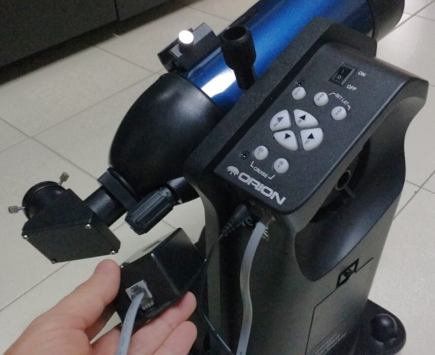
I have tested this project on my Orion Starblast Autotracker mount (also sold as "Skywatcher Virtuoso"):
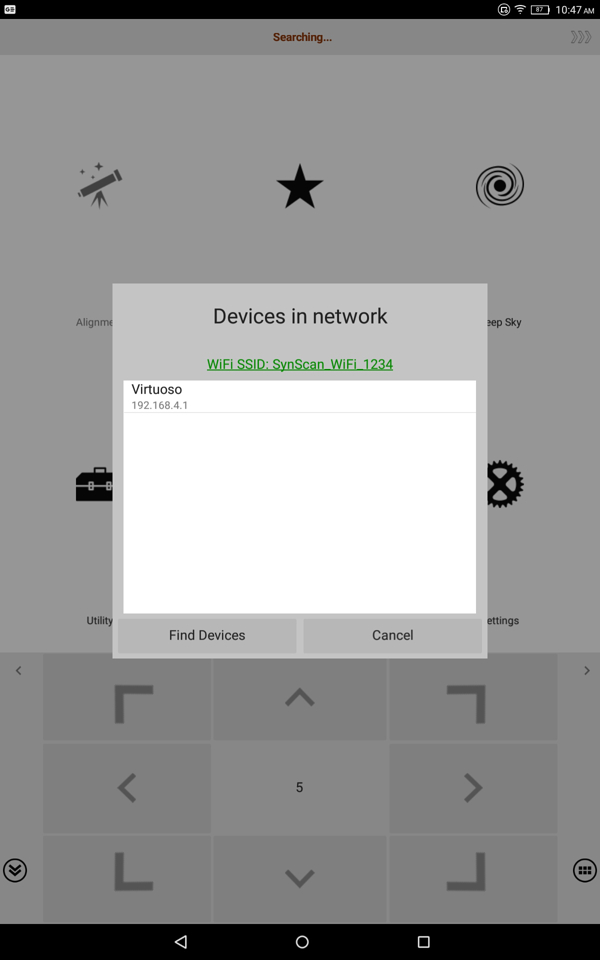
This adapter creates a WiFi network called "SynScan_WiFi_1234". I can connect my tablet to it, and then when I open the Skywatcher SynScan app in my tablet, it will detect my Skywatcher mount, and connect to it:
Note that the name "Virtuoso" was reported by the mount itself, not introduced by this adapter. Also note that no hand controller is needed for this project.
Goto works, including star alignment, tracking, etc. One thing that did not work with my Virtuoso mount are the arrow buttons (for manual movement). My Virtuoso mount comes with these buttons built-in, and even with the adapter+app, I have to use the hardware built-in buttons in the mount for manual movement, because the "virtual" buttons in the SynScan app didn't seem to work. Everything else for goto worked fine though.
- A Voltage regulator / Power Supply
- A NodeMCU ESP8266 development board (I used is this one)
- Three resistors (100 Ohm each).
Although the NodeMCU already comes with an internal Voltage regulator, in many models it does not support input voltages over 10V. For this reason, it's safer (to avoid damaging the NodeMCU) to use an external regulator to drop the VCC voltage from the mount (~12V) down to 5V (the typical Vin voltage the NodeMCU gets from the USB cable).
The 7805 regulator shown in the schematic is a very basic power source, it works, but it will heat up, so it needs a sink for heat dissipation. I recommend instead using one of the better voltage regulators on the market that can take 12V as input and output 5V (like those meant for Arduinos).
Remember that after you install a voltage regulator to power the device from the mount's VCC (12V), you must avoid connecting any computer to the NodeMCU' USB port. You'll risk damaging the USB port of your computer. Also, because the project uses the TX and RX pins of the microcontroller to communicate with the mount, this means you have to upload the software to the ESP8266 first (while it's not connected to anything else but your USB cable), and once programmed, then you can unplug it from the USB cable/computer and then you can plug it to the adapter circuits. If you ever want to re-program the microcontroller, you must first unplug it completely from the adapter circuit.
The order of the RJ-11 pins from top to bottom corresponds to linear order of the bare copper contacts in the actual connector (the ones that will touch the RJ11 cable). Please double check that you have the pin order right, before building anything, measure the voltage between the VCC and GND pins to make sure you get positive 12V, as an iondicator that you indeed have the correct pins for VCC and GND, and that you got the pin order right. If you don't get positive ~12V, you probably have the pin order wrong.
You can probably get the parts for under USD$10, but you do need to be an arduino enthusiast of sorts, in order to use the Arduno IDE to to upload the project's software (see the SkyWatcherWiFi.ino file) to the the NodeMCU ESP8266 microcontroller.
The schematic for building this adapter is:
You will void your mount's warranty if you use this, so this circuit schematic is provided WITHOUT WARRANTY OF ANY KIND, EXPRESS OR IMPLIED, INCLUDING BUT NOT LIMITED TO THE WARRANTIES OF MERCHANTABILITY, FITNESS FOR A PARTICULAR PURPOSE AND NONINFRINGEMENT. IN NO EVENT SHALL I BE LIABLE FOR ANY CLAIM, DAMAGES OR OTHER LIABILITY, WHETHER IN AN ACTION OF CONTRACT, TORT OR OTHERWISE, ARISING FROM, OUT OF OR IN CONNECTION WITH THE CIRCUIT.
You can ask questions or provide feedback here.


