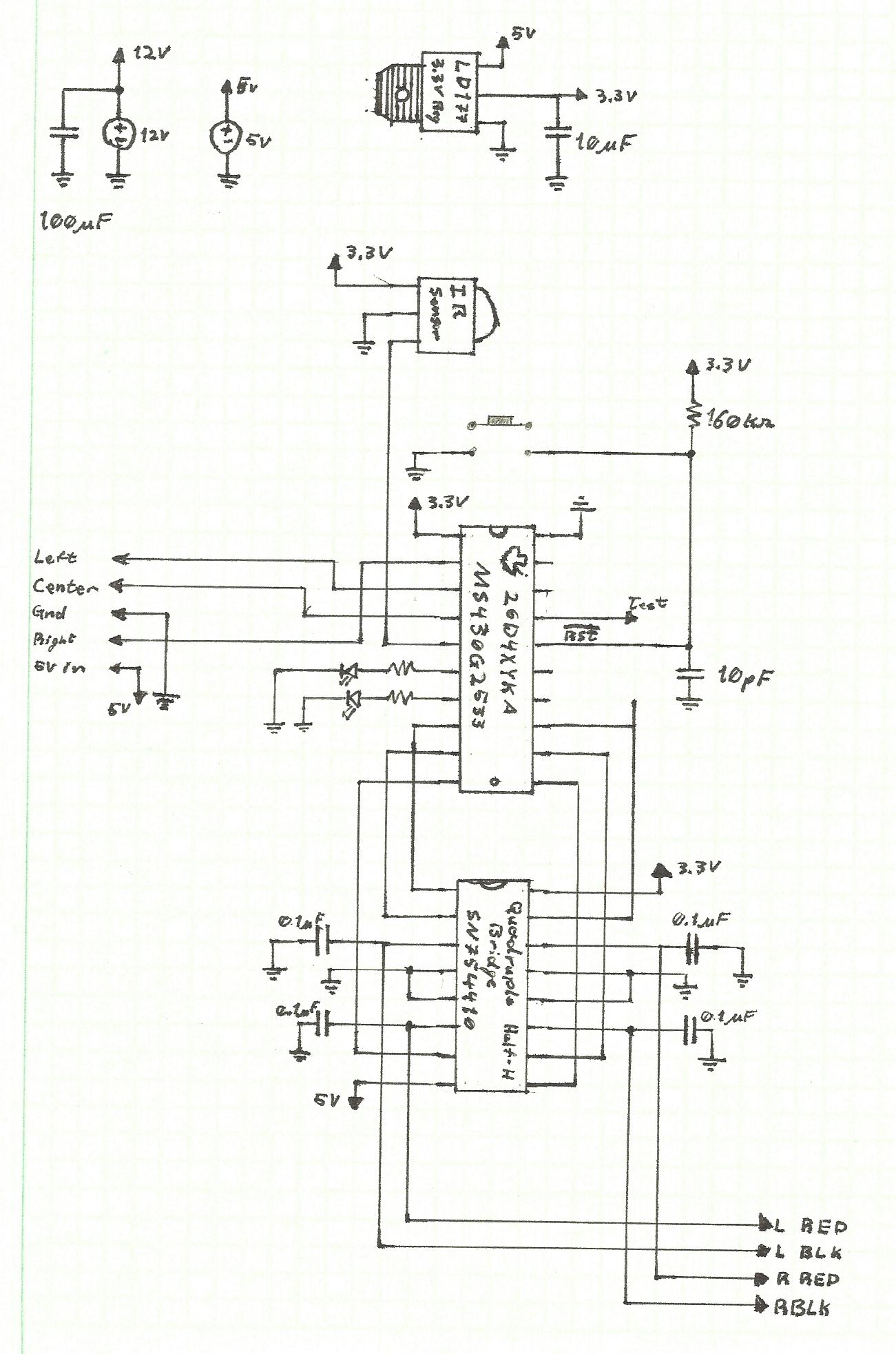
Because this lab will ultimately end in a moving robot in Lab 8, the control circuit for this design included the motor
driving circuit in addition to the connections to the IR rangefinders (the IR signal sensor was included for possible
later use). A full schematic for the design is shown below.
The interface for the IR rangefinder library will allow the user to take a reading from each individual sensor, and include supporting functions like mean and median to allow the user to pull useful data from the rangefinder outputs.
In order to prevent corrupted data values from drastically influencing the measurements from the sensors, the sensor reading functions will add their measurements to either a 4 or 8 value data buffer (depending on timing considerations), from which the user will be able to draw a moving mean, moving median, or some combination thereof.
The MSP430 will use its 10 bit analog to digital converter to make senes of the sensor values. Because the robot will
eventually need effective timing signals to control movement (the waitMiliseconds() function from lab 6) the SMCLK
that will be used to control the timer and converter will be set to 8 MHz. This increased clock speed will require
that every delay function within the converter itself will need to be set to the maximum to avoid loading issues.
While the ADC can run and convert a series of signals in a single call, the modular design where each measurement
would be taken individually requires that only one measurement be taken per call. (The IR signals were, however, wired
to the MSP430 in such a way that a sequential call would read each measurment in a desired order.) Additionally, upon
initialization, the init function will have to fill the data buffer with measured values which could possibley be
accomplished with this sequential read to increase speed.
Finally, if time permits, the library will include a seperate document with a mapping of IR sensor values to particular distances.
The LED Lighting and wall detection will involve a simple call to the right and left sensor measurement functions, then analizing the data to see if the distances are within certain thresholds and adjusting the LED ouptput signals accoridngly. In order to increase the speed and fidelity of the data, the program will likely make two measuremnt calls prior to data analysis. This will phase erronous values out faster by rotating in two new values each iteration. It will also make the program more sensitive to drastic changes in the signal while less sensitive to corrupted values (as fluke measurments are less likely to occure twice in a row).
Because the full implementation of the lab would essentially require a fully functional code library and a baseline set of distance and sensor signal pairings, all functionality aspects were introduced cocurrently. The sensor driver code was implemented with different read functions for each sensor, and the median function was used to pull out a central data value for interpretation by the code. The LED combinations were set so the left sensor corresponded to the red LED, the right sensor to the green LED, and the front sensor activated both.
Once a basic library was constructed and a simple proof of concept program achieved, the sensors were calibrated.
Initially the fillBuffers() method was used to sample 8 data values then return the median, however this produced
inconsistent results. The next approach was then to allow the read, test, repeat loop from the basic proof of concept
program to fill the buffers, place a breakpoint at the top of the loop to stop the code's execution, then to read the
data values. Assuming that I had the robot batteries on durring the testing, this method produced consistent results
that are reported in the included spreadsheet.
In order to ensure that the tests would be consistent with the robot's later use in the maze, distance readings were calibrated using a wooden board that was roughly the same color as the maze wall.
None
