OT adapters
- Ihor Melnyk OpenTherm Adapter
- DIYLESS Master OpenTherm Shield
- OpenTherm-TTL adapter from xyzroe
- Smart Therm (RU): official site, ozon
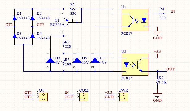
- And others. It's just that the adapter must implement the schema


Box for installation on DIN rail - D2MG, 2 DIN modules.
The 220V > 5V power supply is already on the board, so additional power supplies are not needed.
To save money, 2 levels are ordered as one board. After manufacturing, the boards need to be divided into 2 parts - upper and lower. The boards are inexpensively (5pcs for $2) manufactured at JLCPCB (Remove Order Number = Specify a location).
Some components can be replaced with similar ones (for example use a fuse and led with legs). Some SMD components (for example optocouplers) can be replaced with similar SOT components.
Most of the components can be purchased inexpensively on Aliexpress, the rest in your local stores.
Important
On boards version 1.3 and lower, the GPIO opentherm IN and OUT are mixed up. In the settings they need to be swapped. For example, if the documentation says that IN=4 and OUT=5, then you need to set IN=5 and OUT=4
Wire from the OpenTherm interface from the boiler сonnect to the OT connector, polarity does not matter. The wire must be shielded. For example, shielded twisted pair.
The outdoor temperature sensor must be connected to the TEMP1 connector, the indoor temperature sensor must be connected to the TEMP2 connector.
The power supply for the sensors must be connected to the 3.3V connector, GND to GND.
Caution
Do not connect the sensor power to 5V, this may damage the ESP board.
| LED | States |
|---|---|
| OT RX | Flashes when a response to the request is received from the boiler |
| Status | Controller status. On, not blinking - no errors; 2 flashes - no connection to Wifi; 3 flashes - no connection to boiler; 4 flashes - boiler is fault; 5 flashes - emergency mode (no connection to Wifi or to the MQTT server) 10 fast flashes - end of the list of errors |
| Power | Always on when power is on |